

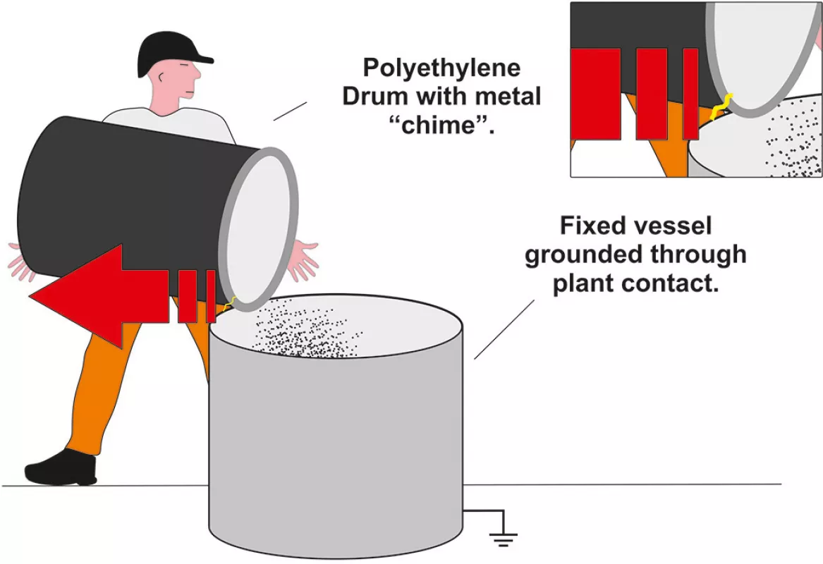
This case study investigates the factors behind the ignition of a combustible dust cloud during a manual powder processing operation. In this example a process operator was tasked with manually tipping approximately 18 kg (40 lbs) of powder from a plastic drum, constructed from polyethylene, into a metal process vessel. The plastic drum contained a combustible powder that had a minimum ignition energy of 12 milli-joules. A metal chime was positioned around the circumference of the top of the plastic drum to provide it with impact protection from daily usage in the plant.
The operator tipped the powder into the process vessel, resting the drum on the edge of the vessel. As he removed the drum from the vessel when the powder was fully deposited there was an ignition of the dust cloud that had formed at the top of the vessel.
The “Why”-Question
It was postulated that the accumulation of electrostatic charge on the chime resulted in a static spark discharge from the chime as it came into close proximity with the vessel when the drum was removed. The vessel was grounded through its own fixed connection to the plant.
In order to verify this theory an experiment was conducted to determine how much electrostatic charge could have been generated by the movement of the powder. 18 kg (40 lbs) of the same powder was tipped from a similar drum into a Faraday cage from which electrostatic charge measurements were taken.
A charge of 3.6 micro-coulombs was measured on the Faraday cage which received the powder. In this case the powder was charged due to the friction caused between the powder and the plastic drum as the powder slid down the inside surface of the drum. A field meter reading of 500 KV/m (the maximum voltage the meter was capable of measuring) was recorded on an isolated area of the plastic drum which would have had the effect of charging the metal chime by induction.
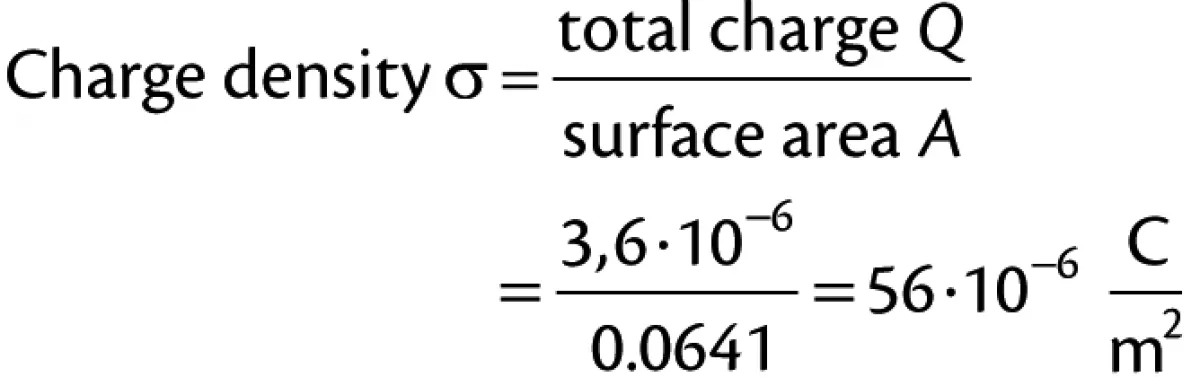
Given the high rate of charge generation caused by frictional charging, the amount of electrostatic charge that could have been induced on the chime would have been limited by the surface area of the same. In this case the surface area of the chime was approximated to 0.0641 m2 (99 in2).
If the total quantity of electrostatic charge (3.6 micro-coulombs) created by the movement of the powder was induced on the chime this would have exceeded the maximum charge density any surface can hold in air. The maximum charge density of a surface in air is equivalent to 27 micro-coulombs per square metre. The total charge density of the chime in this case, theoretically, would have been 56 micro-coulombs per square metre.
|
(1) |
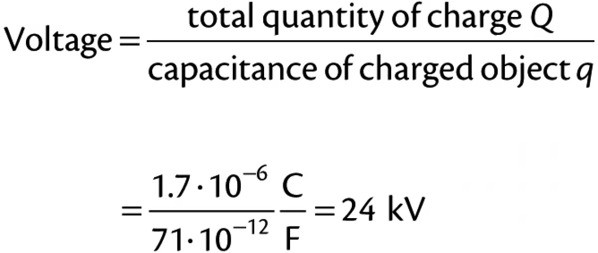
It can be assumed that the maximum charge density, i.e. the total possible amount of charge that could be held on the chime, was achieved through the simple and rapid act of tipping the powder from the drum into the vessel. In this study the capacitance of the chime was estimated to be 71 pico-farads. Knowing these values it is possible to estimate what the potential energy of the spark discharge was.
Taking the above Eq. (1), Q = σ · A, the maximum charge on the chime can be calculated:

|
Therefore, the total charge on the chime would have been close to 1.7 micro-Coulombs. Hence the voltage of the chime would have been in the region of 24 000.
|
(2) |
The average breakdown voltage of air is 3000 volts per millimetre, therefore the voltage of the chime would have been capable of discharging an electrostatic spark from a distance of at least 8 mm (0.3”) to the grounded process vessel.
The potential energy of the chime can be calculated from:

|
where:
| Q | = | charge on chime |
| q | = | capacitance of chime |

|
This exceeds the minimum ignition of the powder which was 12 mJ.
Given that the minimum ignition energy of the powder dispersed in air was 12 milli-joules and that the circumstances of the process proved there would have been significant electrostatic charging of the equipment, and other sources of ignition being eliminated, a static spark caused the ignition of the dust cloud that formed around the grounded process vessel.
So the question is: What actions could have been taken to prevent this explosion?
Counteractions
It’s highly plausible that this operation had been conducted multiple times without a visible incident occurring with electrostatic sparking taking place in previous operations without a combustible dust being present in the spark gap when discharges occurred. This is a common feature of process operations that have suffered from the consequences of a fire or explosion caused by static electricity.
The first place to start is to determine why electrostatic charge was “permitted” to accumulate on the chime. In this case electrostatic charge accumulated on the chime because the chime was electrically isolated from a true earth ground. Had the chime been connected to the grounded process vessel, charge would not have accumulated on the chime. Excess electrostatic charges would simply have found their way to earth. So in accordance with industry guidelines like NFPA 77 and IEC 60079-32-1, the isolated metal component should have had a connection to a verified ground (in this case the process vessel) with a resistance of 10 ohms or less.
Both IEC 60079-32-1 (13.4.1) and NFPA 77 (7.4.1.6) & (7.4.1.4) state: “Temporary connections can be made using bolts, pressure-type earth (ground) clamps, or other special clamps. Pressure-type clamps should have sufficient pressure to penetrate any protective coating, rust, or spilled material to ensure contact with the base metal with an interface resistance of less than 10 Ω.”
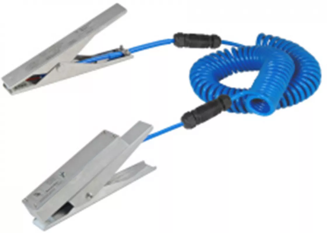
A clamp mounted LED indicates when a connection resistance of 10 ohms or less is made.
|
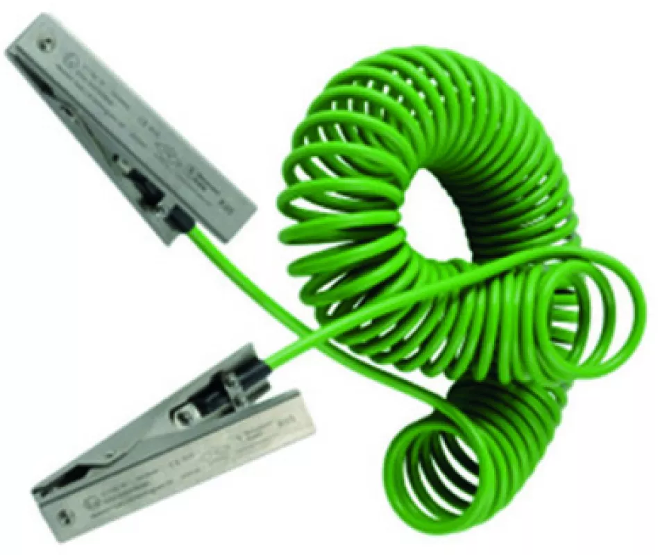
Dual clamp assembly for connecting portable object.
|
Devices like the ones highlighted in the pictures above can be used to connect the drum to the grounded process vessel. At minimum a grounding clamp with FM/ATEX approvals, like the example in the picture on the ight, should be specified so that any physical impedances like paint coatings and product deposits are fully penetrated to make contact with the base metal. The picture on the left shows a device that will inform the operator when a connection resistance of 10 ohms or less between a metal drum and the process vessel has been achieved. This is indicated via a pulsing green LED mounted in the grounding clamp that provides the operator with a simple GO / NO GO instruction to tip the powder into the process vessel.
The use of a plastic drum inside the EX/HAZLOC area also needs addressing. Charging of resistive powders is impossible to eliminate unless specific changes are made to the powder to enhance its electrical conductivity. Very often this is either impractical or not possible to achieve. However, using a plastic container constructed out of a low conductivity material like polyethylene is not recommended in codes of practice as the charge generated during the transfer process remains on the surface of the drum, even if attempts are made to try and ground the plastic drum. Using plastic objects that are poor conductors carries a significant risk of induction charging of other objects in the EX/HAZLOC area. Process equipment and operators if they are in contact with, or in close proximity to, charged plastic objects, can become electrostatically charged. Ideally a metal drum should be used and connected to the grounded process vessel so that no charge is permitted to accumulate on the metal drum.
Last, but not least, all process operators should be grounded through static dissipative footwear that can effectively permit any charge generated during the operation through their own movement bleed off their bodies to the ground. This will ensure they do not carry the risk of discharging static parks from their bodies onto grounded objects.
Codes of practice like IEC 60079-32-1 and NFPA 77 outline what proactive measures can be taken to minimise the risk of a fire or explosion caused by discharges of static electricity. The majority of hazards can be controlled through the installation and proactive use of static grounding devices. Devices ranging from basic grounding clamps right through to ground status indicators with output contacts for interlocking with processes can be specified for a wide range of processes.
■

