

1. Introduction
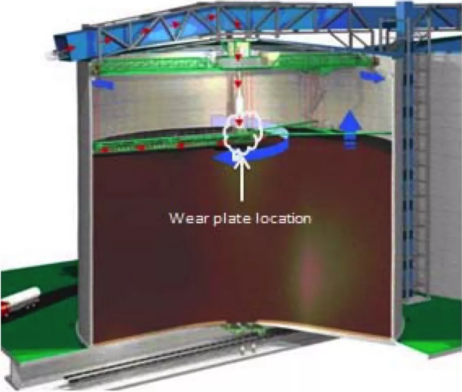
In a Eurosilo system handling coal (Fig. 1), the coal is fed into the silo by means of infeed conveyors on the top of the silo (the direction of coal flow is shown in Fig. 1 with red arrows). The conveyor at the top transfers the coal on to a transfer chute, down through a telescopic chute and is stacked by means of screw augers. These screw augers along with their frames (in green) can be lifted or lowered by a winch system. The auger frame is rotated about the silo axis by rotating the swivelling bridges below the silo roof.
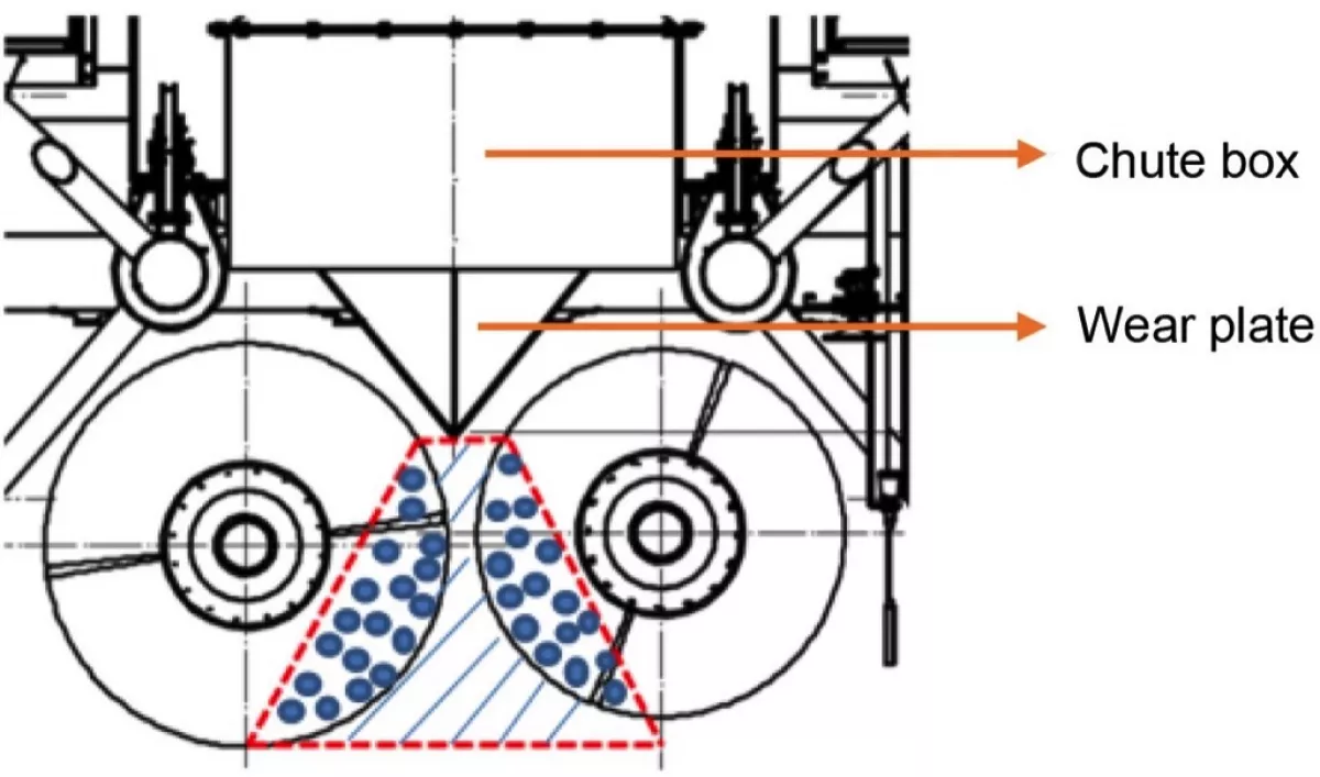
The transfer between the telescopic chute and the screw conveyor is achieved by means of a stone box chute with a wear plate, which changes the direction of the coal towards the screw auger (see Fig. 1). The material stream needs to be controlled and directed to flow towards the zone between the screw augers. The reason is that the screw augers acting over a free surface need a dead zone of material (shaded lines in Fig. 2) between them to propel the material (indicated in large dots) for stacking.
The current transfer chute design in the Eurosilo is a rockbox chute wherein the material forms a bed of particle with a slope and the material starts sliding beyond the slope. The rockbox chute is preferred when the material is very abrasive or for transfers with high rate of discharge when the chute material is expected to wear off quicker. The highest velocity for which any transfer chute has been designed is 15 m/s [1]. In the Eurosilo application the velocity of the materials varies between 15 m/s to 34 m/s at the retracted and expanded position, respectively. No studies have been found on design and analysis of chute design such a high velocity transfer in the bulk material handling field.
The wear-plate-design and the wear plate after a number of years are presented in Figs. 3 and 4. Improved design of this wear plate would eradicate the downtimes due to replacement of the plate and could increase the performance of the machinery inside the silo.
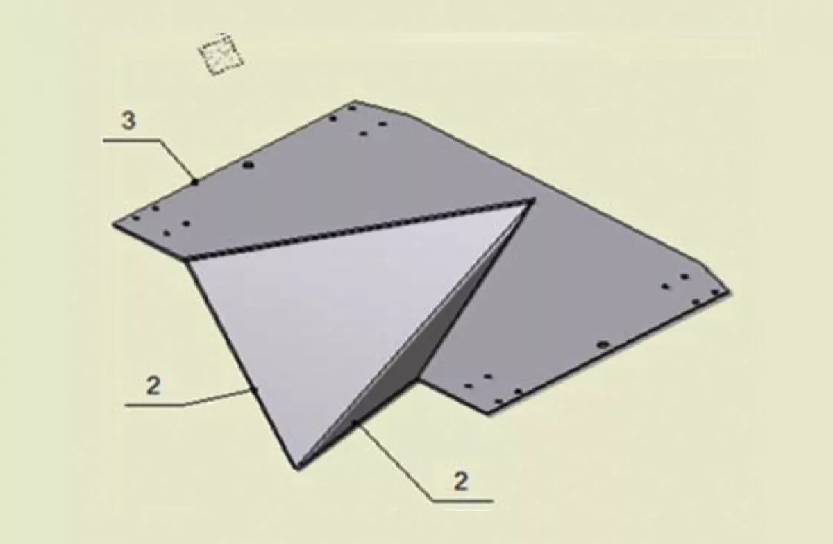
Fig. 3: Drawing of the wear plate. (Picture: © Technical University Delft)
|
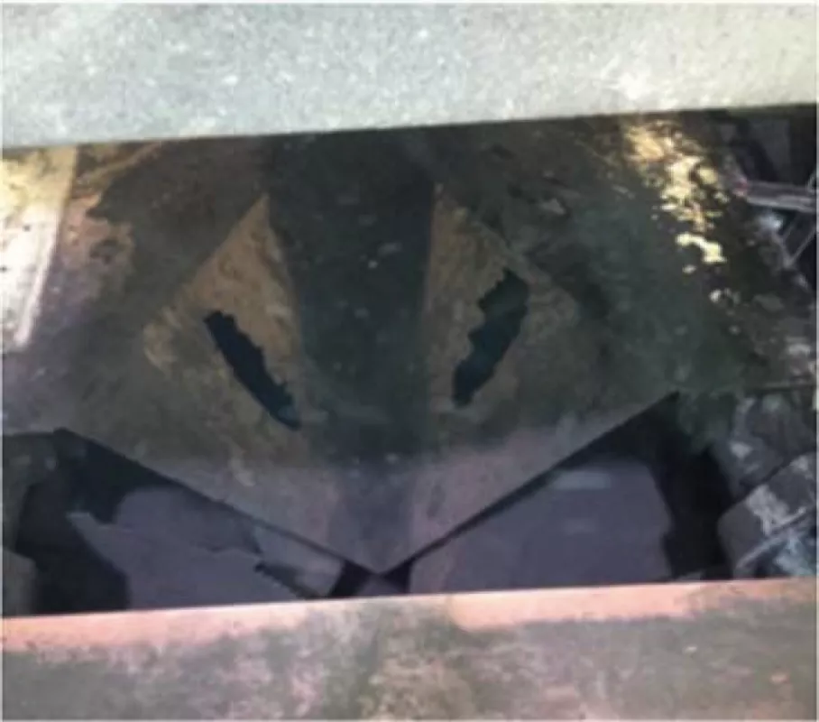
Fig. 4: Photo of failed wear plate. (Picture: © Technical University Delft)
|
The objective of this study is to improve the design of the wear plate chute that facilitates the transfer of coal from the telescopic chute to the screw auger. To achieve this, available literature for designing a new chute is studied and a virtual environment is developed to simulate the interaction between coal and the wear plate. Three chute designs are developed and the performance of these chute designs in terms of wear and flow are analysed using DEM.
2. Literature
2.1. Wear
In general, wear is defined as the removal of material from a solid surface as a result of mechanical action [2]. Archard derived that the total wear volume Vw in the form of a generalized equation applicable for all available wear mechanisms (adhesive, abrasive, corrosive and fatigue wear) and is given by [3]

|
(1) |
where:
| K | = | wear coefficient between the sliding surfaces [-] |
| H | = | hardness of the softer material at the contact [-] |
| Fn | = | normal contact force [N] |
| L | = | sliding distance [m] |
From a thermodynamic point of view, the resultant wear due to the sliding and non-sliding contact is mainly due to the frictional energy dissipated. This is mainly proportional to the applied load and the velocity in case of non-sliding contact and the applied load and sliding distance in case of a sliding contact. The material characteristics, relative velocity, size and shape of the materials also influence the distribution and the dissipation of energy leading to wear. The works of Mindlin and Deresiewicz [4] provided a major advancement in the study of energy dissipation under non-sliding contact. A lot of research has been done to experimentally confirm Mindlin and Deresiewicz’s theory of surface damage due to energy dissipation. It was concluded that the wear volume varied linearly with the energy dissipation during a non-sliding contact (Fig. 5) [5].
![Fig. 5: Wear volume as a function of cumulative dissipated energy [5]. (Picture: © Technical University Delft)](https://www.bulk-online.com/sites/default/files/public/styles/basic_max/public/2023-10/wp_2041.jpg.webp)
Fig. 5: Wear volume as a function of cumulative dissipated energy [5]. (Picture: © Technical University Delft)
|
![Fig. 6: Wear volume as a function of work done by contact force due to sliding contact [6]. (Picture: © Technical University Delft)](https://www.bulk-online.com/sites/default/files/public/styles/basic_max/public/2023-10/wp_2040.jpg.webp)
Fig. 6: Wear volume as a function of work done by contact force due to sliding contact [6]. (Picture: © Technical University Delft)
|
For sliding contact, a similar energetic approach to wear established the correlation between energy dissipated by friction force and the wear volume. The experimental results as shown in Fig. 6 [6] are based on the extension of Archard’s wear theory. It shows the linear relation between wear rate and work done by contact force. The tangent of the line gives the estimation of the wear coefficient.
2.2. Chute Design
Conventional chute designs are mainly performed with the considerations of accelerated flow assuming that the material is always in contact with the chute bottom and side walls [7]. Continuum approach has been used to model the flow of bulk particles within the coal and bulk solid motions are described by a lumped parameter model [8]. For any chute design for transfer of bulk materials under gravity, the basic design principles to be considered are as follows [7].
- Prevent plugging at impact points.
- Ensure that the bulk material accelerates or decelerates sufficiently to match the receiving equipment’s speed.
- Control stream of particles.
- Minimizing abrasive wear on the chute surface.
- Control generation of dust.
For a rockbox chute design specifically, only a few design principles are shallowly discussed in an online forum [9].
Design of transfer chutes using the lumped parameter model, as developed by Roberts [10, 11, 12, 8, 13] has been widely used for different case scenarios. Modelling the particle stream using a continuum approach is on a macroscopic scale in steady state, which makes it difficult for the engineers to conceptualize or visualise complex situations. The properties of bulk solids tend to vary throughout the process which makes it difficult to analyse the design for situations such as cohesion, wear, handling multiple commodities etc. Hence defining very general continuum models applicable for many situations is tedious [14].
3. Method
In recent times, Discrete Element Method has become a widely accepted technique for addressing engineering problems related to the flow of bulk solid materials. The limitation of continuum methods to account for local variation in particle concentration and localized flow behaviour can potentially be modeled using DEM [15]. By now, a vast number of researchers have recommended and used DEM for optimizing and improving design of bulk material handling equipment [15]. In this work a three-stage approach is used:
- Stage 1: Modelling As-Is situation and comparing wear patterns found from DEM simulations with practice.
- Stage 2: Design of three configurations and test their performance against wear in the scenario with the highest material velocities (when the telescopic chute is in extracted position).
- Stage 3: Test the best performing configurations on flow performance in the scenario with the lowest material velocities (when the telescopic chute is in retracted position).
3.1. System Model
The infeed conveyor to the telescopic chute has a capacity of 1600 t/h, with a bulk density of 800 kg/m3 and a belt speed of 2.6 m/s. In reality the wear plate and chute box are attached to the auger frame, and rotate about the silo axis to spread the coal inside the silo. The distribution of particles over the cross-section of the telescopic chute is not homogeneous as the particles are fed by a belt conveyor at the top from one side. Therefore the simulation is done for 4 discrete orientations (0°, 90°, 180° and 270° about silo axis) to understand the wear pattern in the chutes at different positions.
The retracted height of the telescopic chute is 10 m, and the longest (extracted) height is 61 m. The respective maximum particle velocities in vertical direction are 15 and 35 m/s.
3.2. Stage 1: Modelling As-Is Situation
The Hertz-Mindlin (no-slip) contact model was used with EDEM 2.6.1 for particle-particle contact (p-p) and extended with Archard wear for the contact between particles and geometry (p-w). The latter involves both the concepts of Mindlin and Deresiewicz and Archard (Eq. 1 in section 2) and records the energy dissipation at the surface and the wear volume.
![Table 1: DEM input properties - Coal & Steel, partially based on [16][17][18].](https://www.bulk-online.com/sites/default/files/public/styles/basic_max/public/2023-10/wp_2049.jpg.webp)
The input properties used are given in Table 1. The particles are spherical and the distribution in size has a minimum diameter of 5 and a maximum of 50 mm. Both these sizes present 20% of the number of particles. The wear pattern varies with every position of the auger frame, but by overlapping the pictures of each of the positions the concentration of wear in the simulations becomes alike the real wear plate (Figs. 7 and 8).
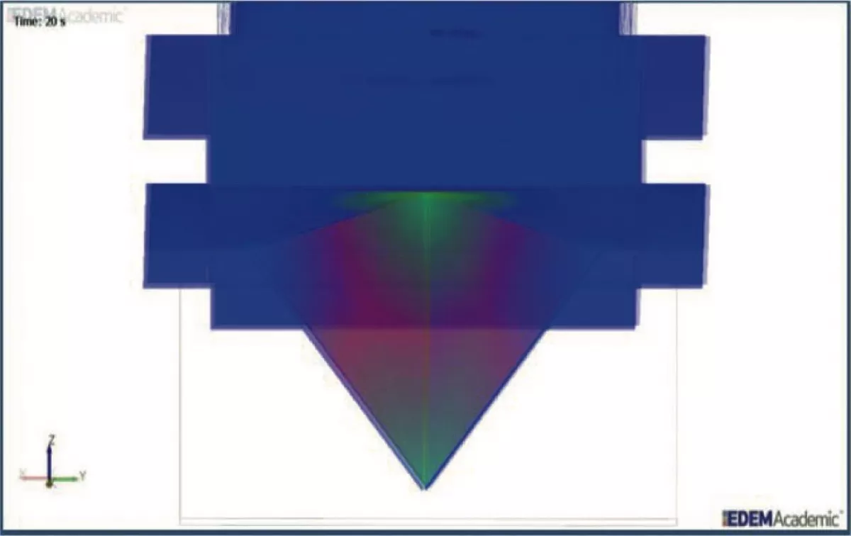
Fig. 7: Simulated wear (superposed from 0, 90, 180 and 270 deg). (Picture: © Technical University Delft)
|
![Fig. 8: Real wear profile work done by contact force due to sliding contact [6]. (Picture: © Technical University Delft)](https://www.bulk-online.com/sites/default/files/public/styles/basic_max/public/2023-10/wp_2038.jpg.webp)
Fig. 8: Real wear profile work done by contact force due to sliding contact [6]. (Picture: © Technical University Delft)
|
3.3. Stage 2: Three Transfer Chute Designs
The limitation in space is given by the auger and auger frame dimensions which are optimised for capacity. Therefore the maximum chute height can be 2.54 m. The three designed concepts are shown in Fig. 9. Their performances, simulated with identical settings as Stage 1, are discussed in Section 4.
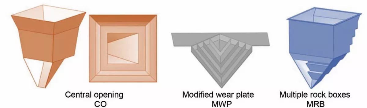
Evaluation of the concepts will be done by assessing the three key performance indicators: Wear volume, discharge velocity and the totalled normal and tangential cumulative energy.

