

Conveyor belting is one of the most expensive components on a conveyor system and a fully functional conveyor system is crucial to the operation of a mine or plant. With the ever increasing cost of mining operations it has become of cardinal importance to ensure the safe and efficient running of the conveyor systems. Belt replacement and unplanned downtime could have a detrimental effect on any operation.
It has therefore become critical to be able to protect conveyor belting and to be able to accurately predict remaining belt life. This will not only safeguard against unplanned breakdowns and loss of production but also put the end user and manufacturer to better plan for future belt requirements, thus reducing required inventory and increasing mechanical availability.
Why Condition Monitoring?
Condition monitoring has gone a long way towards achieving this. Through the use of ever changing and advancing technologies it has become possible to more effectively perform condition monitoring. The result is more reliable systems and information.
The most important reason for doing condition monitoring on any belt is to ensure the safe and most cost effective operation of the conveyor system. Through effective monitoring producing reliable results is it possible to ensure the longevity of any conveyor belt, reduce unplanned stoppages due to breakdowns and ensure more accurate stock planning.
How?
There are a myriad of systems, tools and procedures for doing condition monitoring each with its own advantages and disadvantages. From simple visual inspections to highly sophisticated and very expensive 24/7 on-line systems.
With the aim to increase belt life and availability, the two key areas to concentrate on is most likely the measurement of belt wear and protecting the belt against longitudinal rips.
This paper will concentrate on some of the latest technology available for rip detection and wear or thickness measurement.
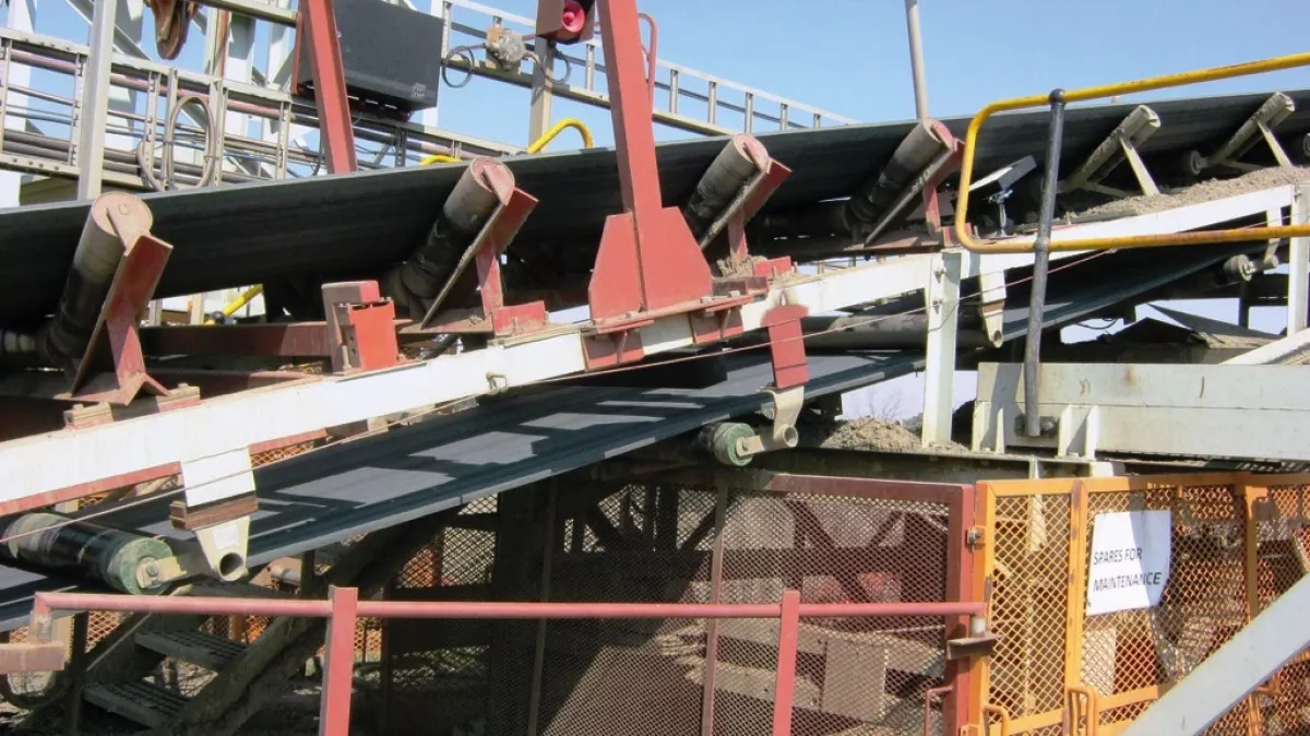
Belt Rip Detection Systems – Current Situation
There are a number of systems currently available on the market such as electro mechanical systems operating with cables or gates running underneath the belt linked to micro switches and tied into the tripwire system as illustrated in Figs. 2, 3 and 4.
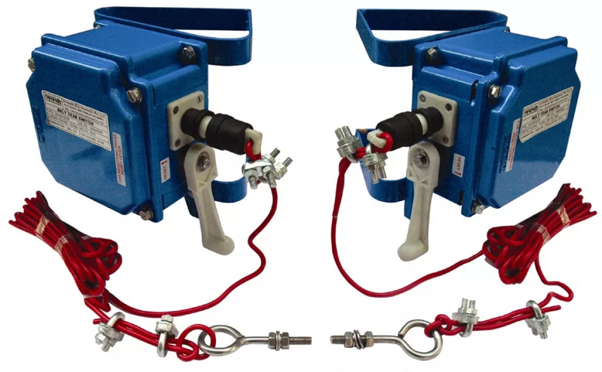
Fig. 2: Example of a cable system.
|
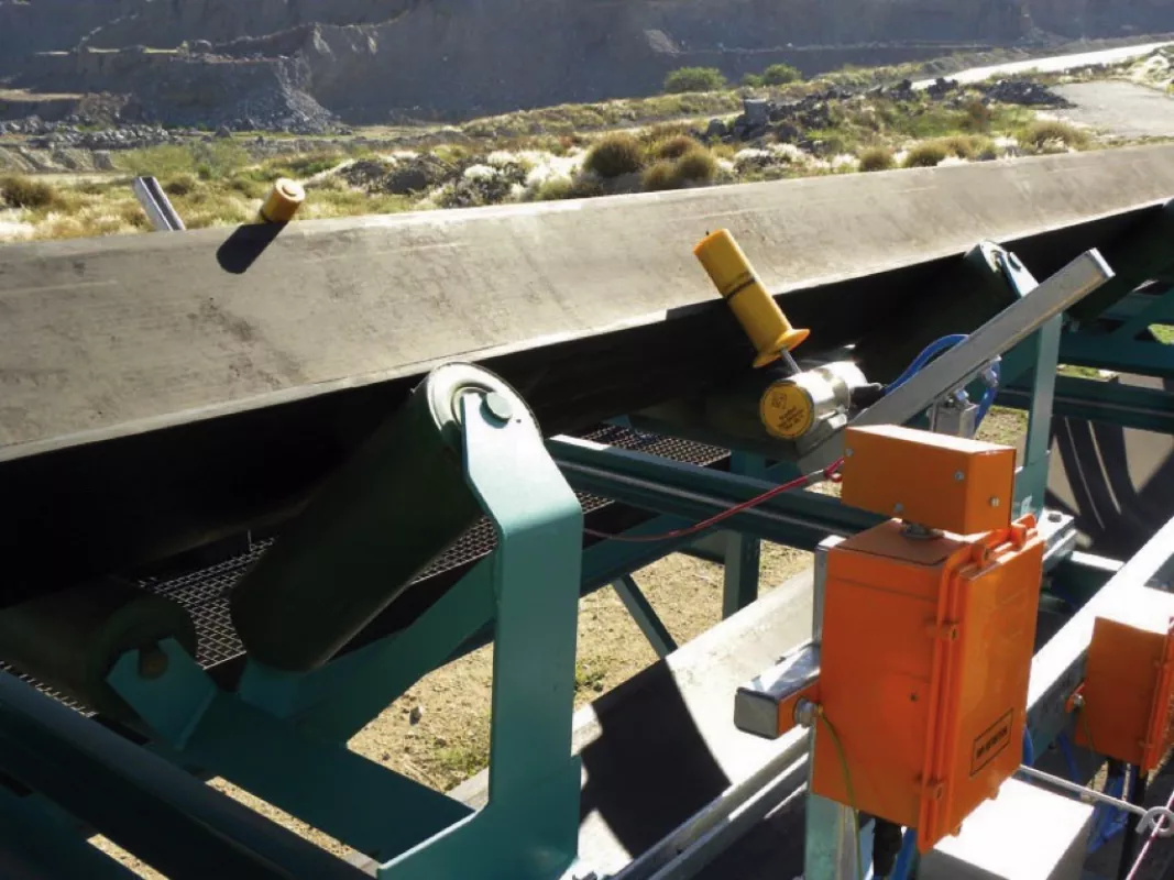
Fig. 3: Example of an installed cable system.
|
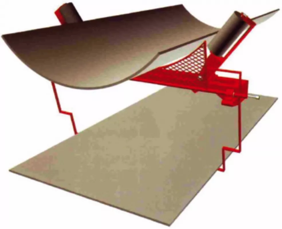
Fig. 4: Example of a gate system. Detects longitudinal rips, top and bottom cover damage, belt misalignment.
|
Sensor Loop Systems
The most commonly used system is the so called sensor loop system. There are numerous variations on this system but the basic principle is the same.
To monitor the steel cord belt, inductive loops are embedded into the belt. Dependent on the belt width, the loops are 320 mm wide and 4,5 mm high and come encapsulated in a rubber flap which can be easily fitted into the belt. These coils may either be fitted underneath (preferably for less stress) or on top of the steel cords with a minimum cover of at least 1 mm of rubber over the steel cords.
The inductive loops are used to transfer electro-magnetic signals from transmitter to receiver which are positioned opposite each other on either side of the belt (Figs. 5, 6).
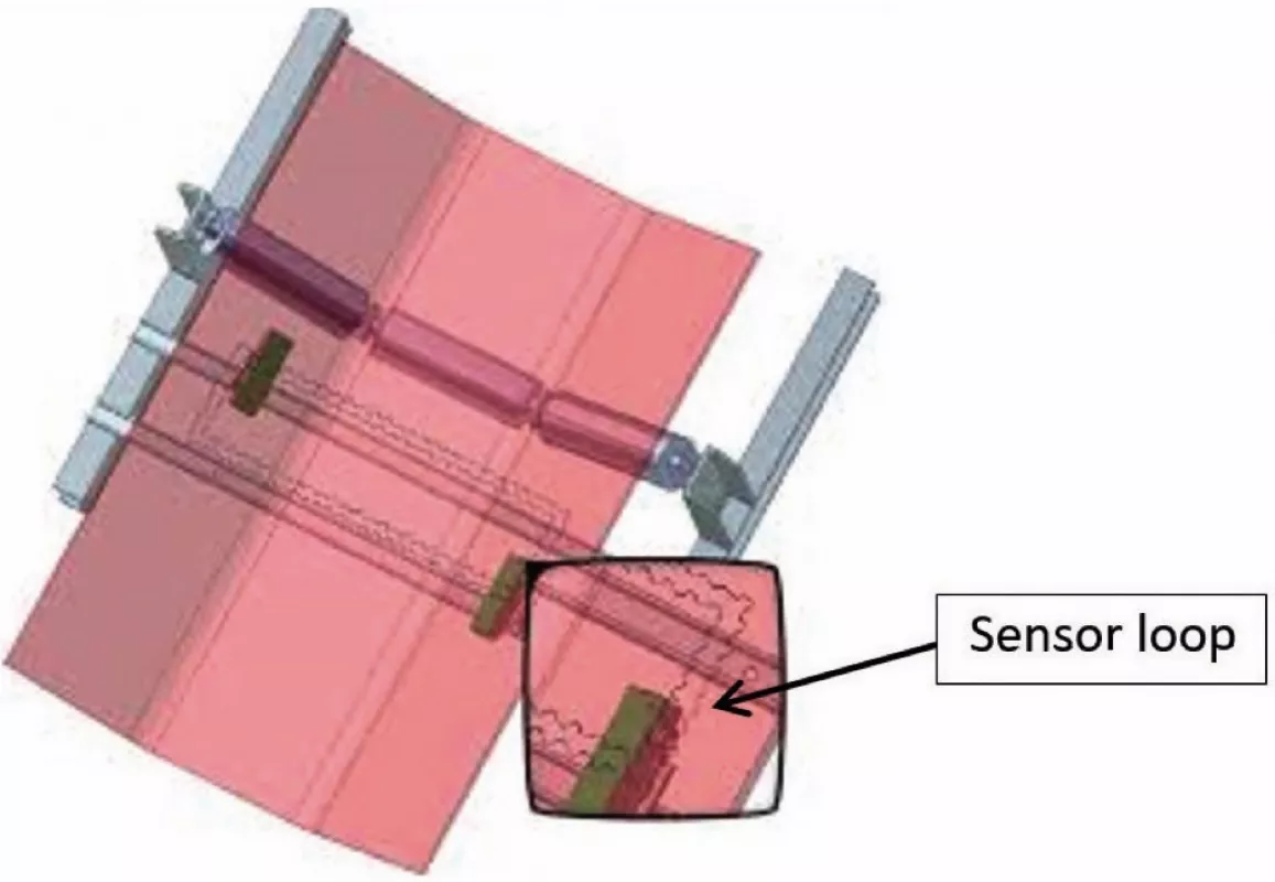
Fig. 5: Sensor loops.
|
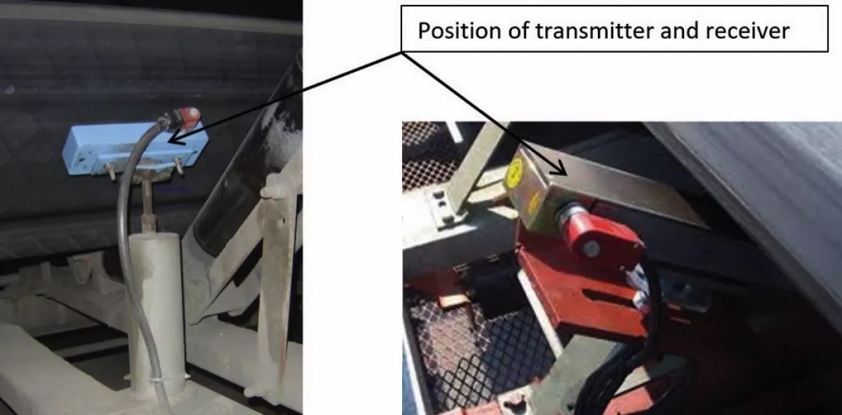
Fig. 6: Transmitter and receiver placement at the belt.
|
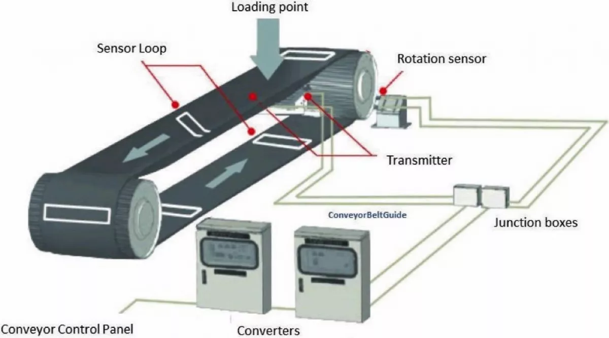
When the belt is in operation, these coils pass over the transmitter/receiver pair and a signal is transmitted via the inductance coil from the transmitter into the receiver (Fig. 7). By knowing the distance between successive coils and the belt velocity, the system can calculate the time interval between coils.
In the case of a belt rip, the appropriate coil will go “open circuit” and thus prevent a signal from being transmitted. The system will acknowledge this as a fault and stop the belt.
The sensor loop embedded in the belt works like a bridge between transmitter and receiver of the system interface. If the belt is ripped the system cannot measure any analog value from the destroyed coil.
After initial installation, the system carries out the “identification run“ and the master control unit will store all the successions of coils in the belt. When finishing the „identification run“ the system knows the internal spaces between every coil in the belt.
The control unit expects the corresponding analog values depending on the speed of the belt within a certain time. If this time is exceeded (missing the expected value) the master switches off the motor drive and stops the belt.

The rip detection system is used to detect longitudinal rips on predominantly steel cord conveyor belts and in very rare cases plied belting and to prevent greater damage to the belt by stopping the belt drives.
Tears usually occur at the loading point and provoked by foreign bodies. Less frequent damage will occur along the length of the belt or at the discharge point.
The belt rip detection system is utilized wherever there is a danger of longitudinal belt rips, in most cases on long overland conveyors or conveyors critical to the reliable operation of a plant or mine.
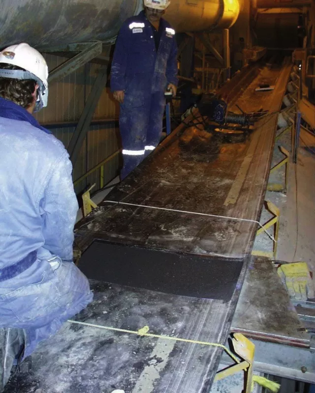
Inductive coils should be selected according to belt width and type of rubber. They can be supplied either as raw rubber plates for installing in steel cord conveyor belting during manufacture or as vulcanised plates for retrofitting for cold and hot vulcanisation Figs. 8, 9). This is time consuming and can take as long as a normal splice (6 to 8 hours).
The total number of coils necessary to protect the conveyor is user dependant. If embedded in short distances (like 15 to 20 m) in case of rip, the maximum tear will only be 20 m. With surface conveyors, the coils are integrated usually every 100 to 200 metres, whereas the distance between coils in underground installations does normally not exceed 50 to 80 metres. For very important and hazard exposed belt conveyors the distance range is 10 to 50 metres.
The system works on the principle of “secondary“ rip detection, i.e. rips are detected only after they have occurred. They cannot be prevented but the damage can be reduced to a minimum.

