

For many years, mining plants have been operating with various problems of differing degrees of severity plaguing the storage and handling of their bulk materials. Vast amounts of time and money have been lost due to downtime, sub-quality products, damage to equipment and excessive wear in hoppers and chutes, simply as a result of the lack of understanding the behaviour and flow characteristics of bulk materials under handling, storage, reclaim and feeding conditions. Building new plants and the expansion of existing plants are expensive, and due to the prevailing fragile economic situation in the mining and allied industries, it is often difficult to allow for bulk solids flow testing and advanced functional design of materials handling systems at the early conceptual stage. Material flow testing and tests on physical models are critical in defining design parameters for bins, transfer chutes, silos and stockpiles, with the cost savings from working designs outweighing the cost of bulk solid flow tests. Unfortunately, flow stoppages and blockages due to arching and ratholing of cohesive materials are common problems in bins and silos. By determining the flow properties of bulks solids and designing materials handling storage facilities based on these flow properties, most flow problems can be prevented.
1. Bulk Material Testing and Typical Results
Good knowledge of the flowability characteristics of bulk materials are essential to successful design, eliminating unnecessary risk and ensuring a smooth transition from the construction to operational phase. For bulk materials with a significant percentage of particles finer than about 4 mm, the cohesive strength of the bulk material is governed by this fraction. Before the bulk strength of a sample is established, the sample needs to be prepared. The sample is screened to ensure only the -4 mm fraction is used for bulk solids flow testing. In general, the samples can be crushed in the laboratory; it is recommended that samples are screened because crushing can influence the internal and wall friction angles of the material. The following material flow test work is recommended for design of typical materials handling components such as chutes, bins, silos, stockpiles and conveyors:
- Particle size distribution analysis of the sample Defines the particle size distribution of the bulk material
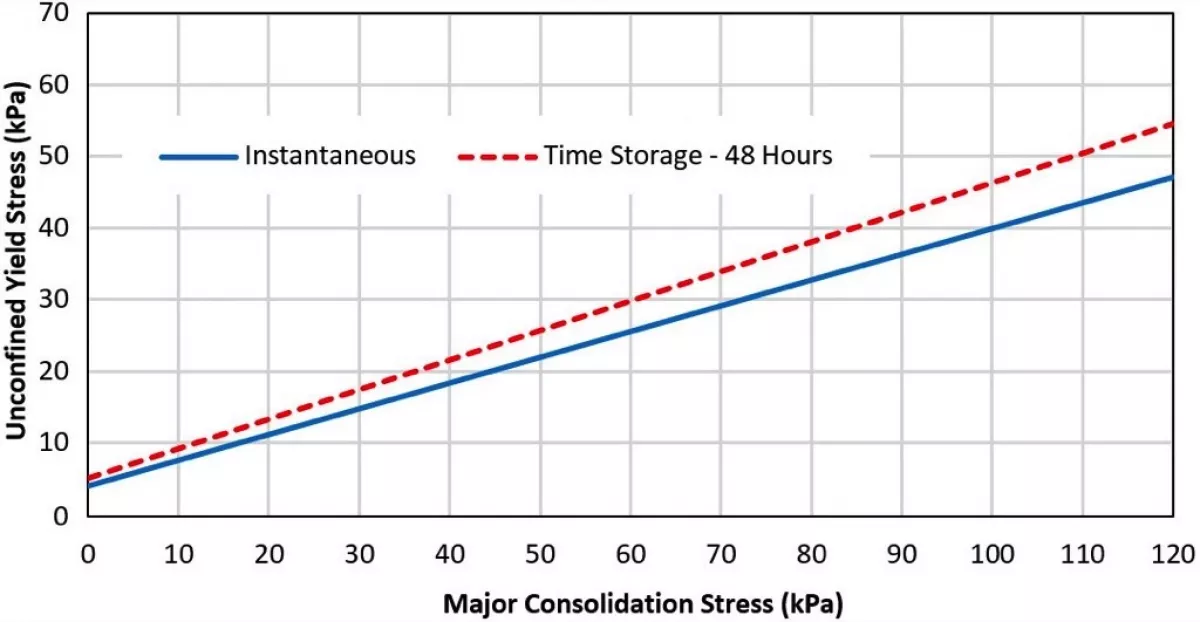
- Jenike instantaneous tests The minimum required mass flow openings and hopper angles for instantaneous flow are obtained. The critical rathole diameters for instantaneous flow are determined and used to design funnel flow storage systems.
- Jenike time storage tests Bulk materials in general gain cohesive strength when exposed to a compressive stress for some time, like in a bin, silo or stockpile. The minimum required mass flow openings and hopper angles for time storage conditions are obtained. The critical rathole diameters for time storage conditions are obtained and are used to design funnel flow storage systems.
- Density and compressibility tests The bulk density values of the sample are determined as a function of range for a range of consolidation pressures. The bulk density design values vary for conveyor loading, live capacity and feeder load calculations.
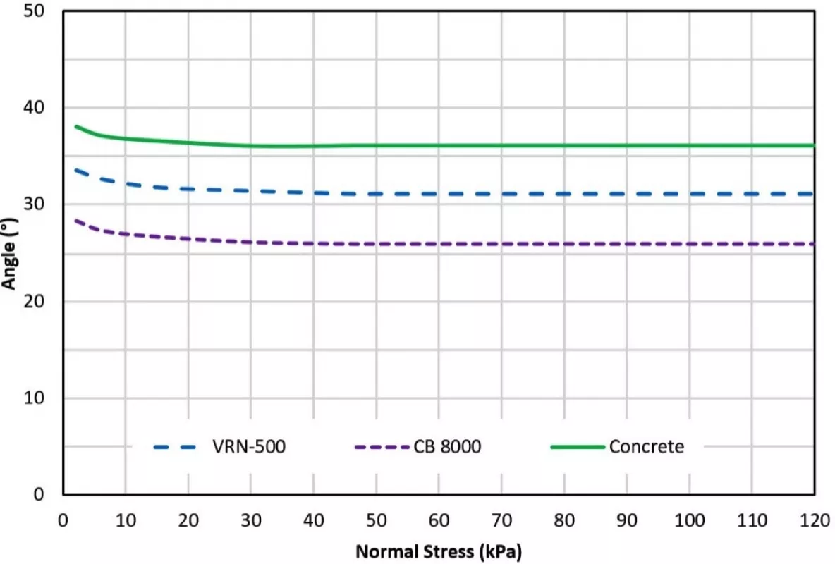
- Jenike wall friction tests for different types of liners The wall friction angles for a specific liner are obtained as a function of normal stresses. The wall friction angles are a required parameter to calculate the minimum openings and hopper angles of mass flow bins.
- Chute friction angle tests for different types of liners The chute friction angle results are used to calculate the build up angles of the bulk material in chutes, as well as the material velocities throughout the chute.
- Discrete element modelling (DEM) testing and calibration A sample of bulk material is tested with a series of scaled tests and a discrete element software package is used to match the test results. The calibrated DEM models can be used to visually design chutes.
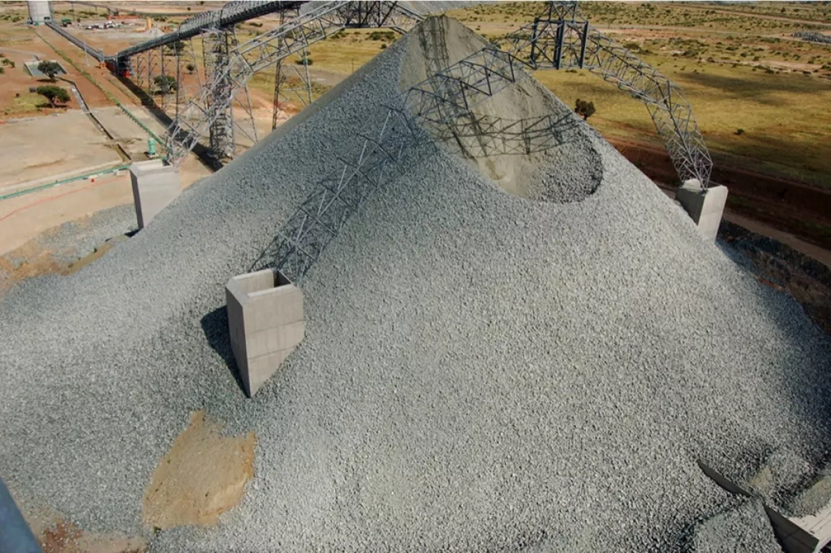
Figs. 2 through 6 show a typical set of bulk solid flow graphs obtained for Platreef material at 2% moisture content.
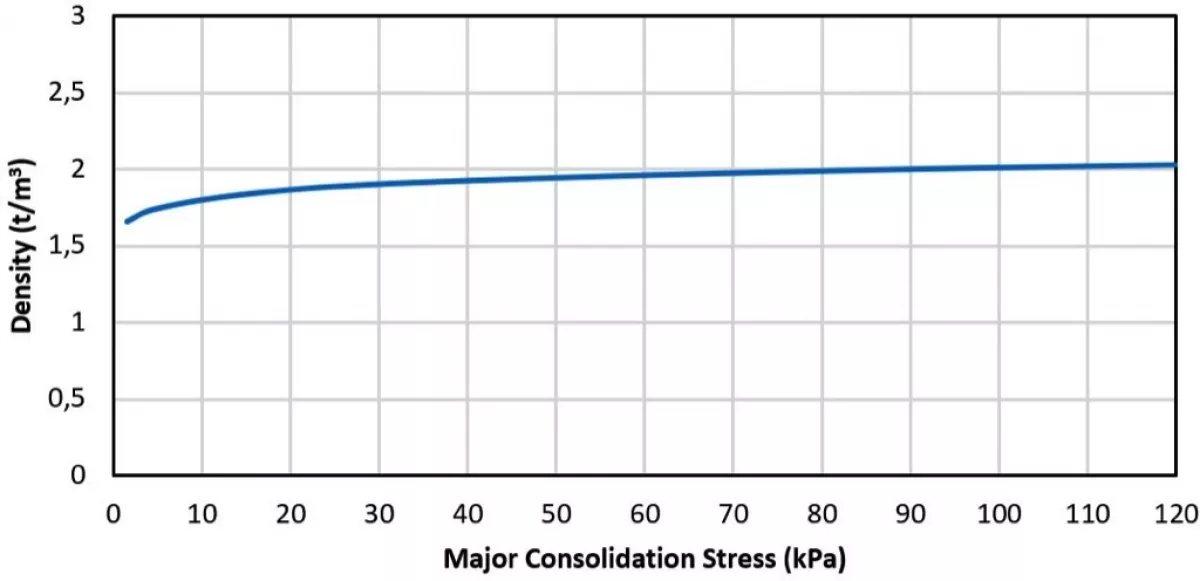
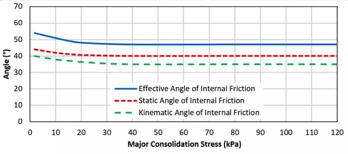
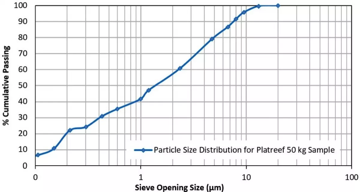
Platreef is a platinum group element and base metal enriched mafic/ultramafic layer situated along the base of the northern limb of the Bushveld Complex in the Rustenburg area of South Africa. From the bulk solid flow graphs, design parameters are determined, which in turn are used for the design of materials handling systems.
1.1 Mass Flow Design Parameters
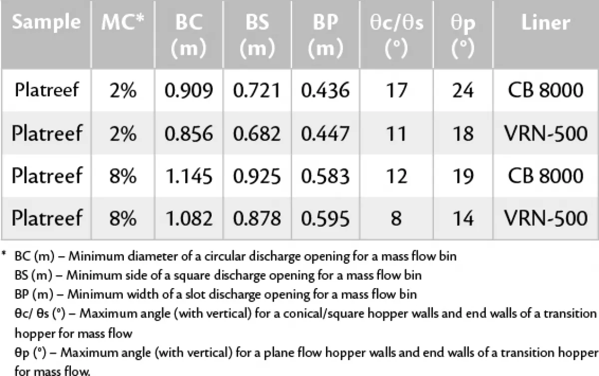
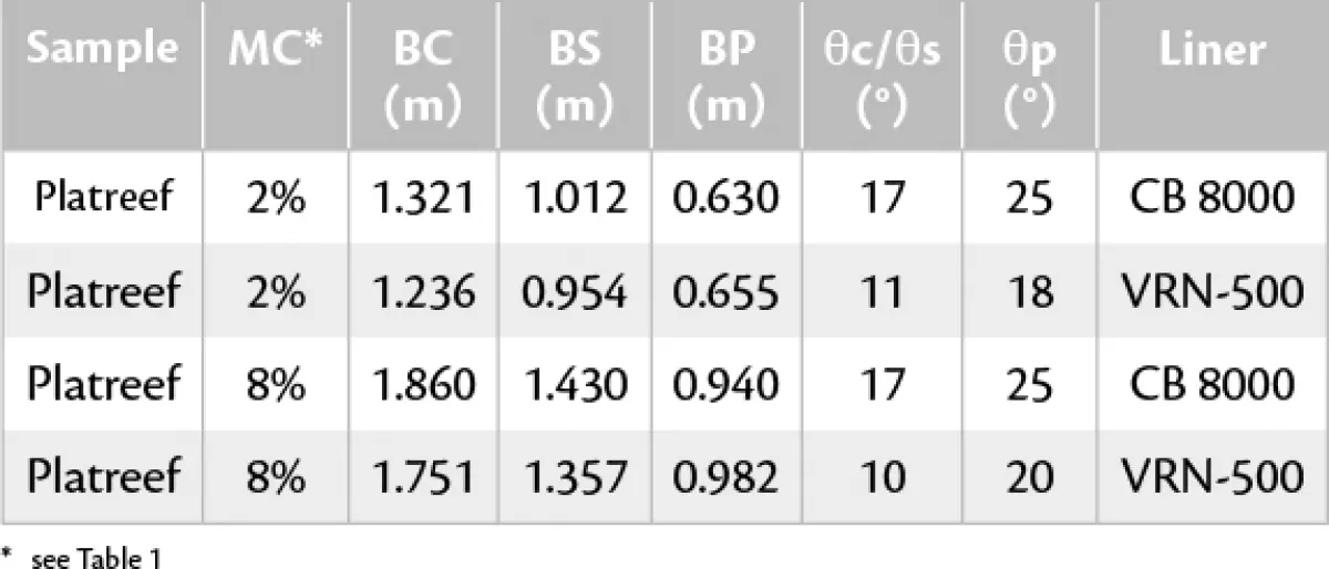
For mass flow, the bulk solids are in motion at every point within the bin whenever material is drawn from the outlet. Mass flow guarantees complete discharge and the flow rates are predictable. It is a first in first out principle and remixing of the bulk solid can occur during discharge should the solid become segregated while filling the bin. Tables 1 and 2 were determined from the bulk solid flow graphs.
1.2 Funnel Flow Design Parameters
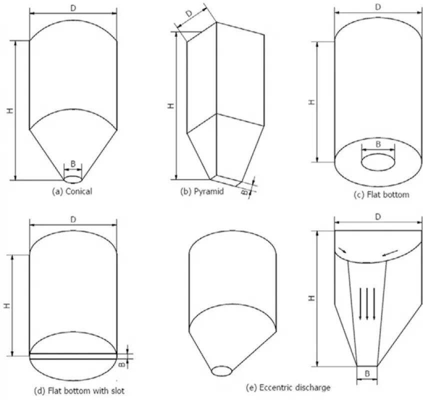
Funnel flow works on a first in last out principle and maximum levels of segregation are present. Typical funnel flow storage facilities are stockpiles, flat or tapered bottom bins and silos. Funnel flow storage facilities are prone to form stable piping diameters above feed openings reducing the overall live capacity under gravity flow conditions if designed incorrectly. Flow promotion aids are often required to initiate and maintain flow. It should be noted for funnel and expanded flow storage facilities that the critical piping diameters below represent the -4mm particle size distribution. For functional design these values can be adjusted or reduced depending on the percentage fines in the incoming stream of material. This will lead to large capital savings during the design phase. There are many different points of views and theories regarding these reductions factors by experts in industry. Fig. 7 presents the calculated critical rathole diameter results for Platreef material at 2% moisture content.

2. Design of Bulk Materials Handling Storage Facilities
The following procedures are required for the design of a materials handling plant consisting of bins, silos, gravity reclaim stockpiles, feeders and transfer chutes:
- Determination of the strength and flow properties of the bulk solids for the worst case flow conditions most likely to be expected in practice.
- Determination of the bin, silo, gravity reclaim stockpile, feeders and transfer chute geometry to create a functional design to the correct live capacity and flow pattern requirements.
- Estimation of the pressures and loadings through bin, silo and stockpile discharge openings, as well as the normal forces on the wall. This is required for feeder power consumption and start-up calculations as well as structural design.
A bin (silo, bunker) generally consists of a vertical cylinder and a sloping, converging hopper. The first step in the process of bin selection is to decide on the type of bin required. There are three types of bins:
- Mass flow
- Funnel flow
- Expanded flow
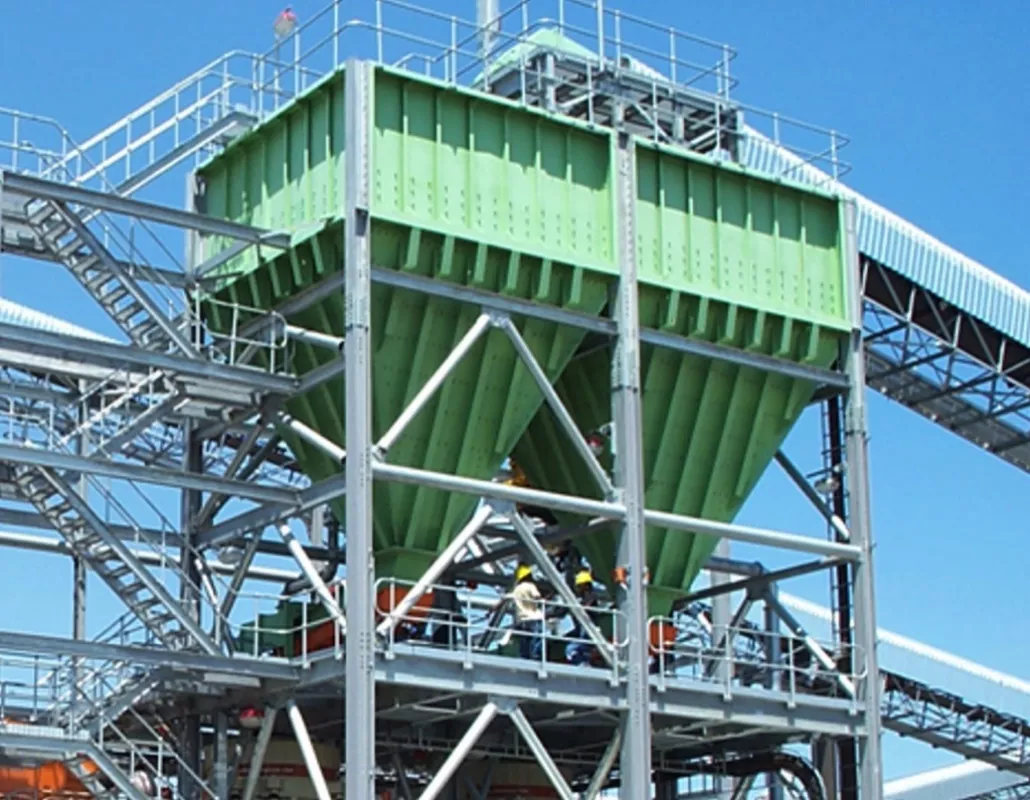
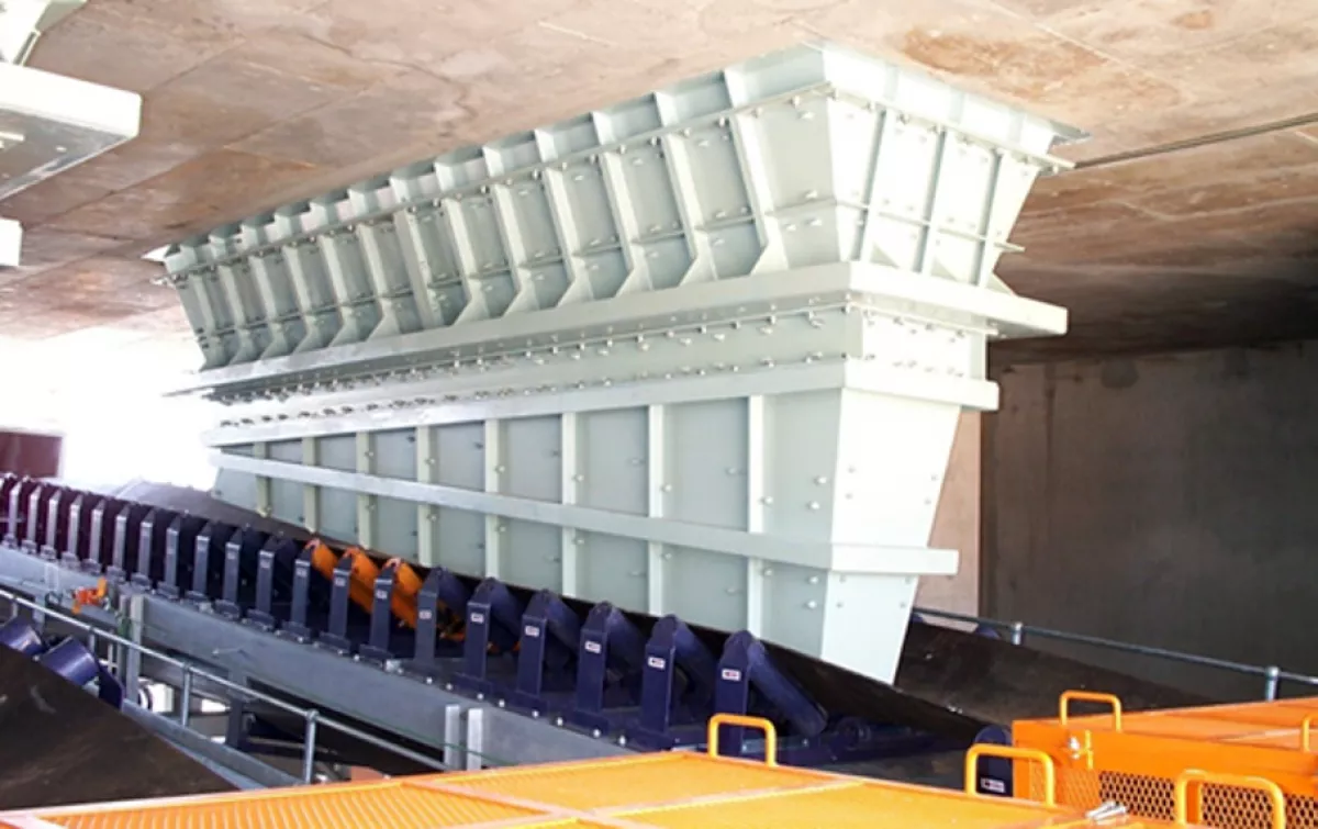
Fig. 8: A mass flow bin containing platinum material.
|
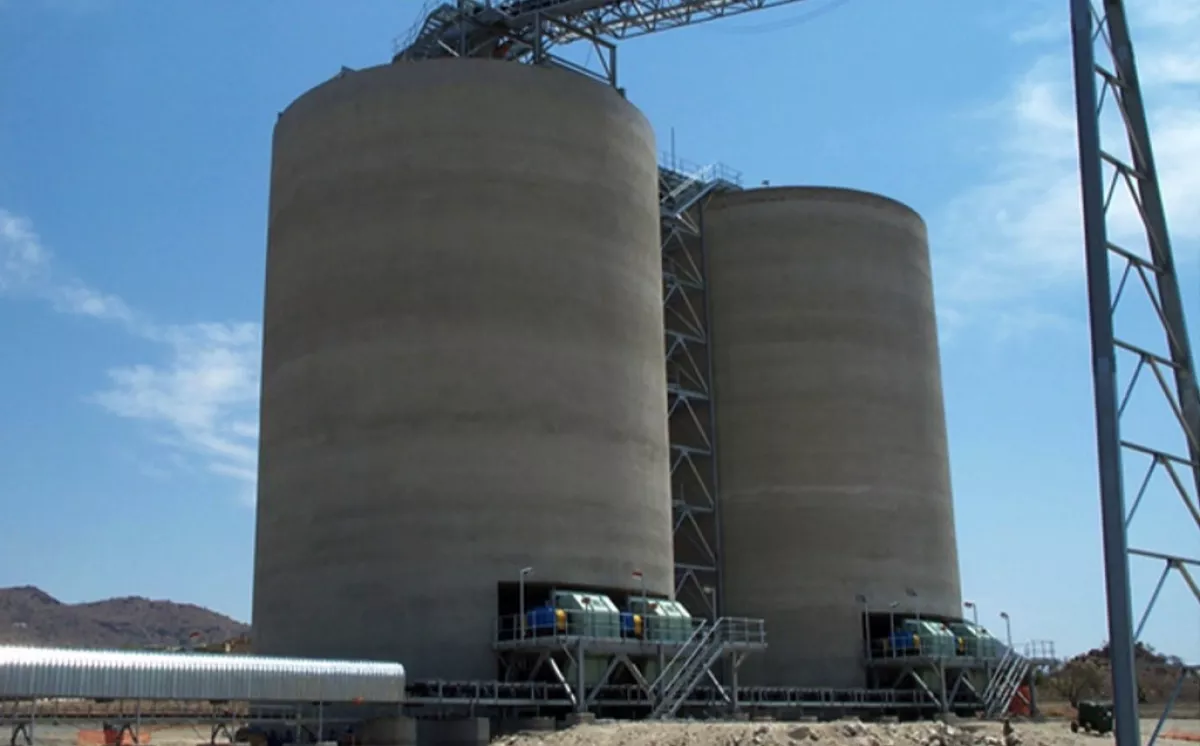
Fig. 9: An expanded flow flat bottom silo containing platinum material.
|
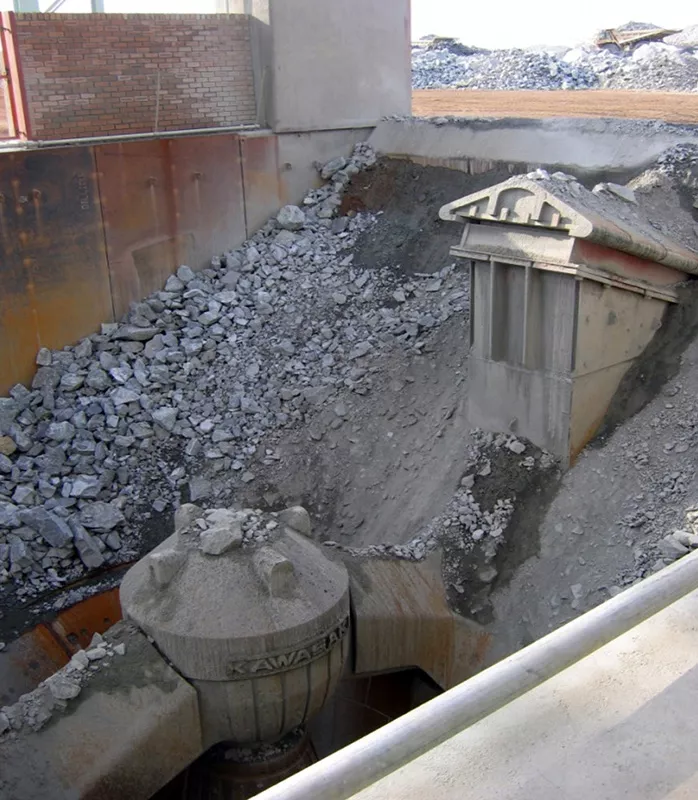
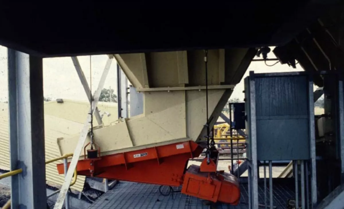
Fig. 10: Funnel flow bin for run-of-mine platinum ore (crusher opening).
|
2.1 Mass Flow Bin Design
In a mass flow bin, the hopper is sufficiently steep and smooth to cause flow of all the bulk material without stagnant regions whenever any bulk material is withdrawn. The two important design parameters that define a mass flow bin are the half hopper angle, α, and the minimum slot width, B.
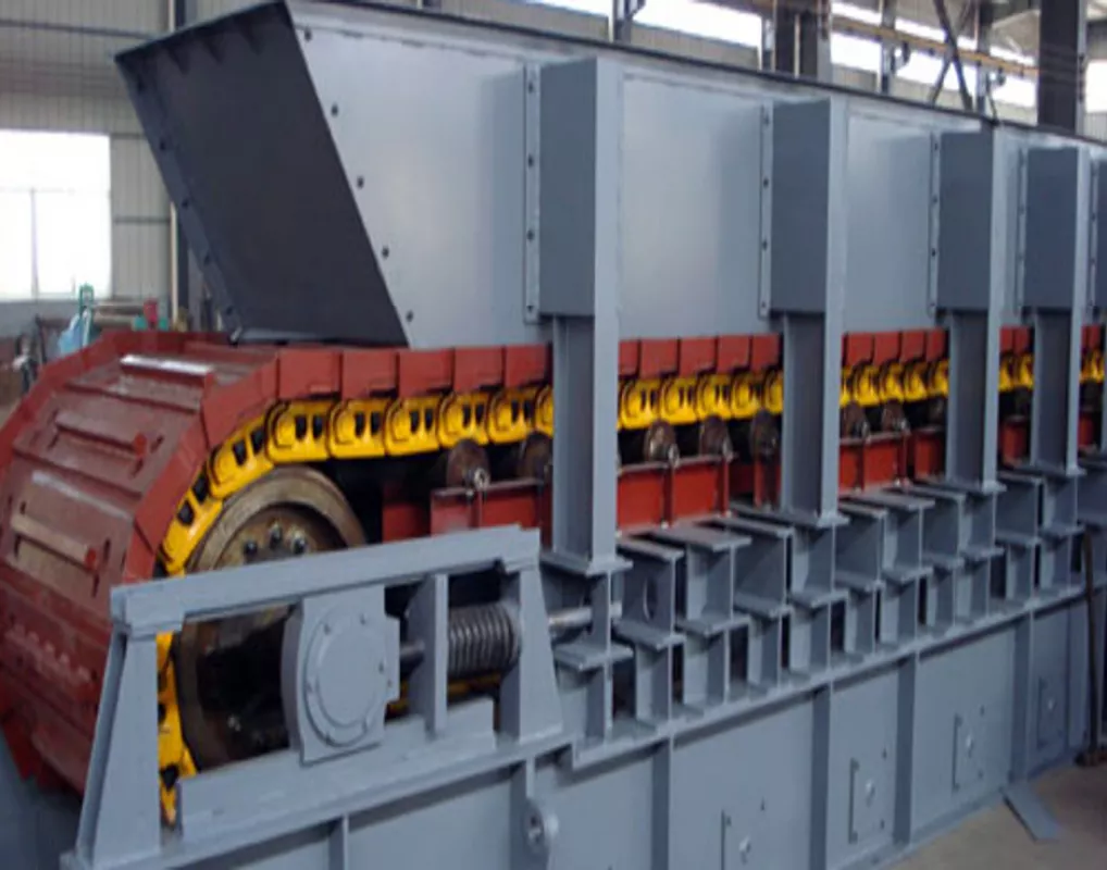
Mass flow bins, examples of which are shown in Fig. 11, have certain advantages. The flow is uniform, and the discharge flow rate is practically independent of the head of solids in the bin. This frequently permits the use of volumetric feeders for feed rate control. Since stagnant regions are eliminated, low level indicators work reliably. Even though the solids may segregate at the point of charge into the bin, segregation of the discharge is minimised by the first in first out flow sequence associated with mass flow. This flow sequence also ensures uniform residence time and de-aeration of fine powders (Roberts, 1991, 1998). Mass flow bins are recommended when handling cohesive materials, powders and materials that degrade with time, and when segregation needs to be minimised. Ledges and protrusions are not permitted in a mass flow hopper. In addition, the outlet must be fully effective. If the hopper is equipped with a radial door or knife gate, the door-gate must not prevent flow of material along the hopper walls. If a feeder is used, it must draw material across the full outlet area. Mass flow bins can be used for in-bin blending.
2.2 Funnel Flow Bin Design
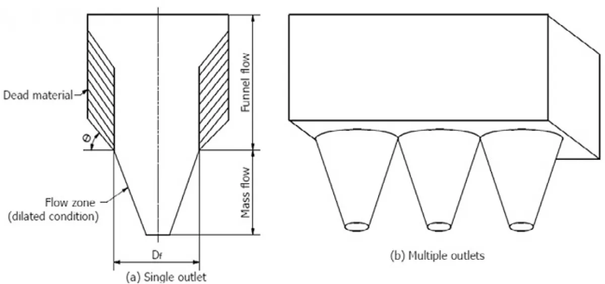
Funnel flow occurs when the hopper is not sufficiently steep and smooth enough to force material to slide along the walls. It also occurs when the outlet of a mass flow bin is not fully effective. Examples of funnel flow bins are shown in Fig. 12. The width B should be sufficient to prevent a stable arch from forming across the opening.
In a funnel flow bin, bulk material flows towards the outlet through a channel that forms within stagnant material. With non-free-flowing solids, this channel expands to a diameter that approximates the largest dimension of the outlet. When the outlet is fully effective, this dimension is the outlet’s diameter, for all opening types such as circular or diagonal if the outlet is square or rectangular. The channel will be stable if its diameter is less than the critical rathole diameter. With free-flowing solids, the flow channel expands at an angle that depends on the effective angle of internal friction of the material. The resulting flow channel is generally circular with a diameter in excess of the outlet diameter or diagonal. When the bin discharge rate is greater than the charge rate, the level of solids within the channel drops, causing layers to slough off the top of the stagnant mass and fall into the channel. This spasmodic behaviour is detrimental with cohesive solids since the falling bulk material packs on impact, thereby increasing the possibility of arching. With sufficient cohesion, sloughing may cease, allowing the channel to empty out completely and form a stable rathole. Aerated solids charged into this empty rathole may overflow the feeder (Roberts, 1991, 1998).
When a fluidised powder is charged directly into a funnel flow channel at a sufficiently high rate and is withdrawn at the same time, it has no opportunity to de-aerate. It therefore remains fluidised in the channel and floods when exiting the bin. A rotary valve is often used under these conditions to contain the material, but a uniform flow rate cannot be ensured because flow into the valve is erratic. In general, funnel flow bins are suitable only for coarse, free-flowing or slightly cohesive, non-degrading solids, when segregation is unimportant.
2.3 Mass Flow and Funnel Flow Limits for symmetrical Bins
Jenike developed the limits for mass and funnel flow, assuming a radial stress field exists in the hopper (Jenike, 1961, 1964). The limits for conical and plane-flow hoppers depend on the hopper angle, α, the effective angle of internal friction, δe, and the wall friction, φw. The effective angle of internal friction and wall friction are determined by laboratory tests; once these values are established, the hopper angle may be determined as
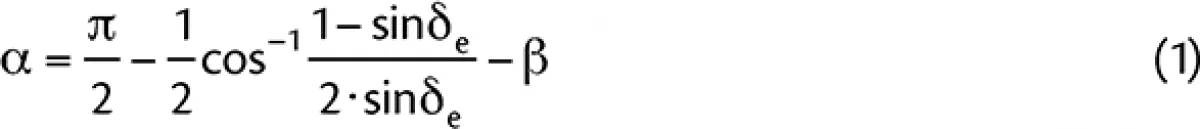
|
where
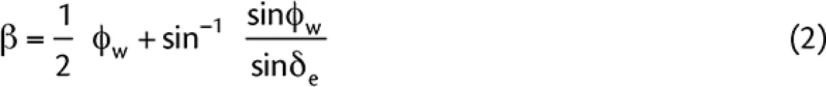
|
For plane-flow hoppers, the discharge is by planar converging motion, and the bounds between mass and funnel flow are much less severe than for conical hoppers where the discharge converges radially inward. Therefore, for conical hoppers, the hopper angle is steeper than that of plane-flow bins. Since the work of Jenike for flow in a hopper is based on the radial stress field theory, the influence of the surcharge head due to the cylinder height of the bin is ignored when a flow pattern is developed (Roberts, 1991, 1998). The aim in mass flow design is to determine the minimum hopper angle, α, to ensure flow along the walls, and the minimum hopper opening dimension, B, to prevent material from arching in the bin. The critical opening dimension, Bcr, is obtained for the condition when the stress in the arch, σ1
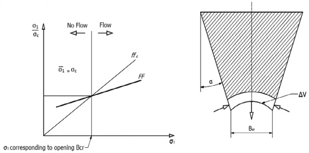
The following equation was developed by Jenike to determine the critical opening dimension, Bcr
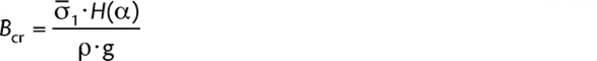
|
The function H(α) from Jenike and Leser (1963) is an arching thickness parameter and may be represented as
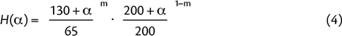
|
where:
| m | = | 0 for rectangular hoppers |
| m | = | 0 for conical hoppers |
| m | = | 0.9 for square openings |
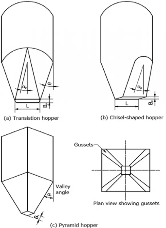
2.4 Maximum Hopper Angles for Mass Flow
A bulk material sliding on a bin wall encounters frictional resistance proportional to the tangent of the wall friction angle. This angle generally depends not only on the roughness of the wall but also on the pressure that the bulk material exerts on the wall. For many hard wall surfaces, the friction angle decreases as the bulk material contact pressure increases. This pressure, which varies with its position in the bin, is usually lowest at the outlet. Therefore, the hopper angle required is often dictated by the outlet size selected. The recommended maximum hopper wall angles, αp (long slotted openings) and αc (conical or square openings), are measured from the vertical plane of the bin (Hui, 2012). To minimise headroom, consider changing the slope of the hopper wall as a function of position. For example, if a conical hopper is to be designed with an outlet diameter of 1 m and the recommended αc is 10° at 1 m diameter and 20° at 2 m and larger diameters, use two conical sections. In the lower section where the diameter varies from 1 m to 2 m, use a hopper angle of 10°. Above the 2 m diameter, use a hopper angle of 20°. This principle is applied in designing hyperbolic bin shapes. Often, both continuous flow and time friction tests are run on a material. If the solids adhere to the wall with time, the time test results will indicate an increase in friction angles. To overcome this time effect, the hopper walls should be made steeper, as recommended, otherwise, flow aids should be used to promote flow.
2.5 Calculation of Effective Head of a Silo
The critical rathole diameter, Df, is a function of the major consolidating pressure that acts on the solids in the bin. It is convenient to express this pressure in terms of hf, the effective consolidating head of solid in the bin, as
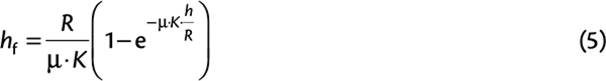
|
where:
| R | = | Hydraulic radius of the cylindrical portion of the bin – ratio of cross- sectional area to circumference; |
| R | = | B/4 for a circular cylinder of diameter B or a square cylinder of side B |
| μ | = | Coefficient of friction between the stored solid and the cylinder walls |
| K | = | Ratio of horizontal to vertical solids pressure. A value of 0.4 is usually acceptable within cylinders |
| h | = | Height of the cylindrical portion of a bin |
A less conservative method is to calculate the critical rathole diameter for a bin or silo by determining the flow and initial loads for the channel of effective withdrawal. The initial loads can easily be converted to an effective head and the corresponding critical rathole diameter can be interpolated from the test work results. In general the effective withdrawal for a stockpile or silo is equal to the effective angle of internal friction plus a 10° safety factor for live capacity purposes. Silos and stockpiles should be emptied on a regular basis to prevent dead material build-up from consolidating and growing in capacity. If this is not achieved the withdrawal angle can reach approximately 45° plus the effective angle of internal friction divided by two. If a stockpile or silo develops a rathole, the withdrawal angle is usually between 0° – 15° with the vertical plane, depending on the cohesiveness of the material. Therefore ratholing can (and will!) drastically reduce the live capacity of an expanded flow storage facility.
2.6 Feeders
Feeders are used to control the rate of material discharge from a bin (hopper, silo and bunker) outlet. They must not be confused with conveyors, which simply transport material from one point to another. Common feeders include screw, belt, apron, rotary ploughs and vibrating feeders. The rate of material being discharged is most commonly controlled volumetrically from these feeders; therefore, it is also critical to use the correct bulk density from test results to ensure the required flow rate is met.
The volume of material per time unit may be varied by changing the feeder speed, amplitude or frequency or the front opening area of discharge. Several of these feeders may also operate gravimetrically and the mass of material per time unit is measured and controlled.
Proper feeder selection depends on a number of factors based on the bin choice and feed requirements. Two major objectives for efficient feeder design are uniform withdrawal of the material from the entire bin outlet area and minimising the material loads on the feeder, all within the process requirements of flow rate and layout. In order to ensure that the outlet is fully effective, the choice of feeder must be based on the outlet size and shape. If the requirements of bin selection dictate that the outlet be slotted, the feeder must increase in capacity in the direction of feed to ensure a uniform draw of material across the entire outlet. The choice of feeders is generally limited to a belt, apron or a vibrating feeder in the mining industry (Hui, 2012).
If the feeder’s capacity does not increase correctly, the feeder will tend to draw material from either the front or back of the opening of the bin, resulting in a high velocity flow channel having a diameter only one to two times the width of the slot. This may become critical when feeding powders, since the powder may remain fluidised when passing the channel and flood on exiting the bin. Feeders should also be designed to have sufficient torque to break away initial shear forces and have sufficient installed power to operate at running conditions.
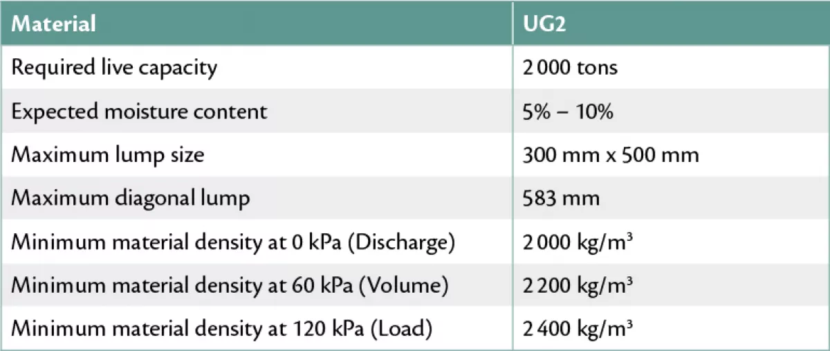
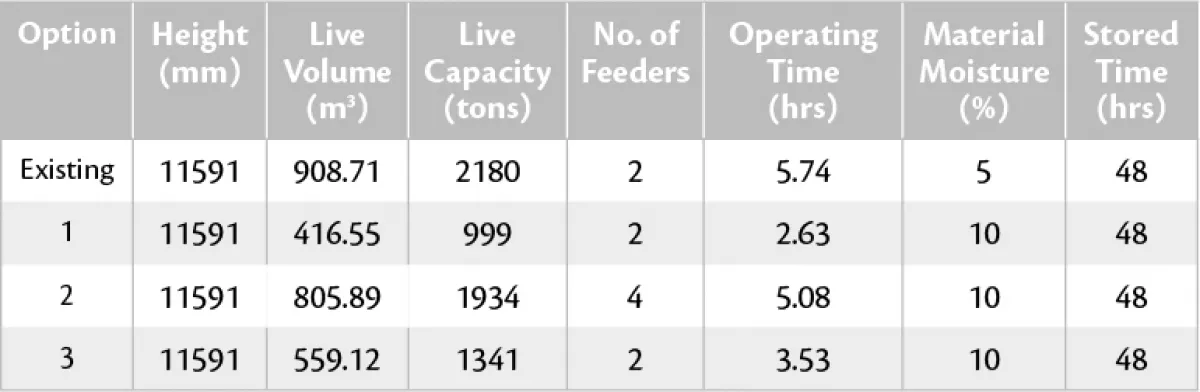
3. Case Study: UG2 Stockpile
A platinum mine was operating an existing stockpile approximately 12 m high with UG2 material at 5% moisture content. The stockpile was fed with an incoming conveyor and the bulk stream feeding the stockpile contained a -4 mm fraction percentage between 25% to 30%. The stockpile was reclaimed by gravity flow with two vibrating feeders (expanded flow). The stockpile did not experience any problems such as ratholing and arching of material in the mass flow chutes. Eventually the stockpile faced a changeover of material and new underground UG2 material at 10% moisture content was stockpiled. Besides the higher moisture content the new material also contained a higher percentage of the -4 mm fraction that ranged between 35% to 40%. With this new UG2 material at 10% moisture content, the stockpile experienced regular problems. The mass flow chutes blocked frequently affecting production output, and the stockpile’s live capacity was reduced due to ratholing. A site investigation was conducted and the aim was to determine solutions with minimum downtime for handling a more cohesive UG2 material than that originally designed for. Bulk material flow testing was conducted for instantaneous and time storage conditions by means of Jenike shear testing and the results were evaluated and used to evaluate the stockpile, see Table 3. For this paper, only the mass flow parameters are considered.
The following factors and risks were considered:
- Arching problems
- Live capacity
- Downtime during installation of proposed solutions
- Possible improvements and modifications
- Cost
- Bulk materials testing and flowability
3.1 Stockpile Properties
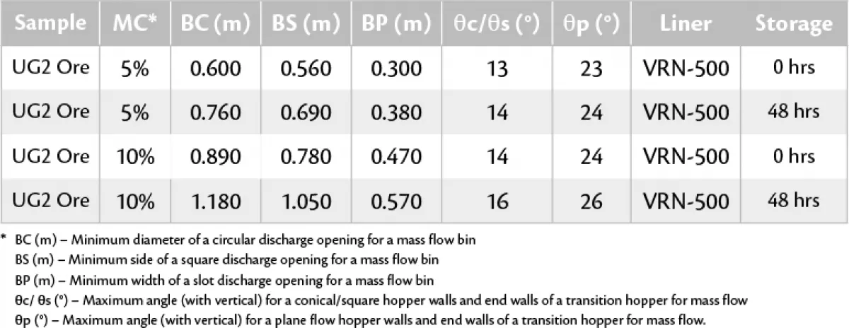
The material and stockpile properties used in conjunction with the mass flow test work are presented in Table 4.
The material properties and design parameters obtained from test work for the 5% and 10% moisture content material were compared. This was used to predict the difference in flowability of the UG2 ore. It was evident that the 10% moisture content material was more cohesive. The existing mass flow chute properties onto vibrating feeders were as follows:
- Square opening width = ± 900 mm
- Hopper angle with the vertical for VRN-500 = 14°
Since material could be stored for periods longer than 48 hours, the mass flow design parameters for time storage conditions were selected. For UG2 ore at 5% moisture content the following design parameters are important to achieve mass flow:
- Minimum square opening width required = 690 mm
- Minimum hopper angle required with the vertical for VRN-500 = 14°
- Angle of repose = 34°– 36°
The stockpile with mass flow chute interfaces feeding onto vibrating feeders worked sufficiently and no arching occurred for the 5% moisture content UG2 material. All the design parameters adhered to the test work results. The result is depicted in Fig. 18. The mass flow requirements for UG2 ore at 10% moisture content and 48 hour time storage conditions were as follows:
- Minimum square opening width required = 1 180 mm
- Minimum hopper angle required with the vertical for VRN-500 = 16°
- Angle of repose = 40° – 45°
How the stockpile would look with the above featured results is presented in Fig. 19.
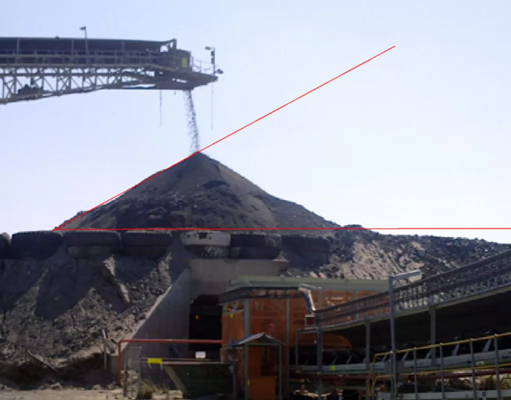
Fig. 18: Existing stockpile – run-of-mine ore – angle of repose = 34° for 5% moisture content.
|
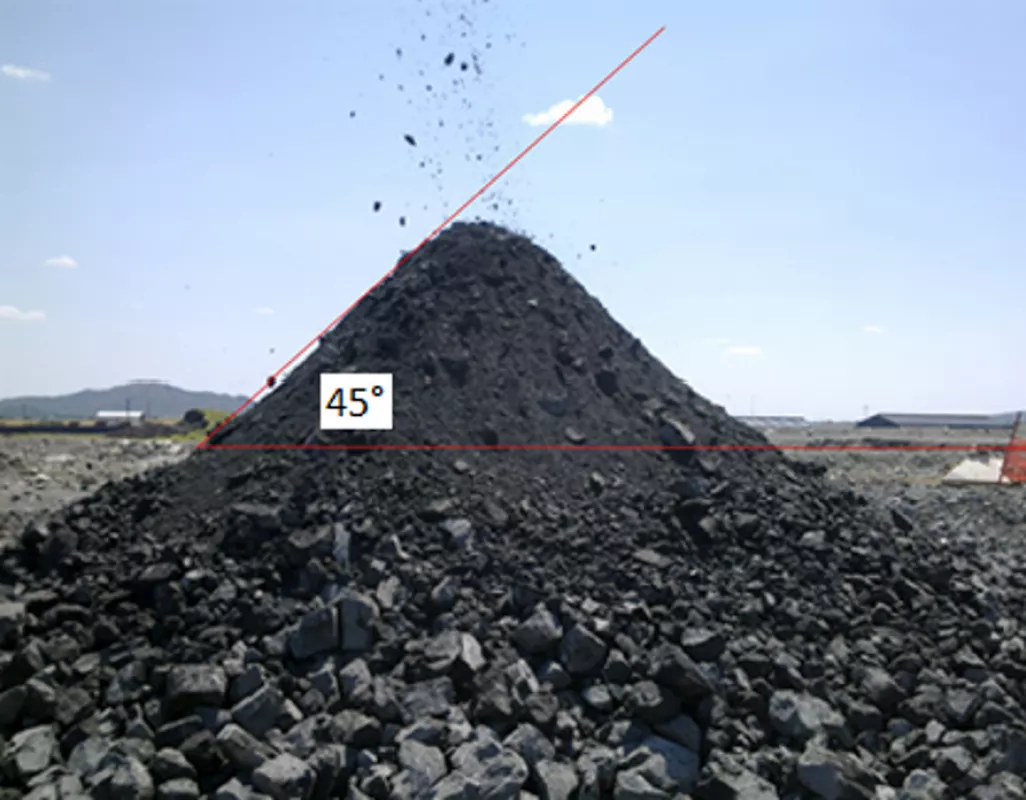
Fig. 19: Temporary stockpile – run-of-mine ore – angle of repose = 45° for 10% moisture content.
|
4. Conclusion
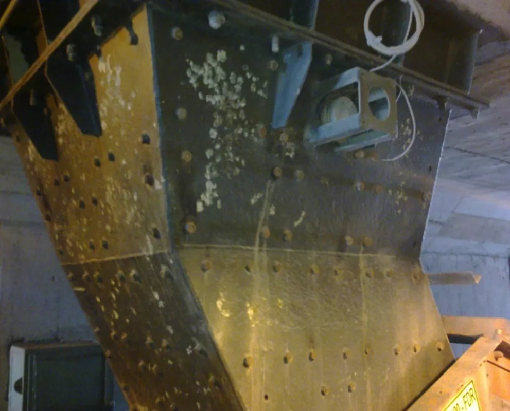
From the test results it was concluded that there are large variations between the flowability of the 5% and 10% moisture content material. The stockpile with 5% moisture content material worked efficiently and had sufficient operational live capacity. Once the stockpile was in operation with 10% moisture content material, the stockpile withdrawal tended to rathole and the mass flow chutes blocked frequently. The existing mass flow chutes with openings of 900 mm wide did not adhere to the requirements of the test results which specified square opening widths of 1 180 mm. The hopper angles were not affected according to the test work, but the VRN liners inside the chute were corroded, affecting the wall friction. A functional design was done to predict the ratholing effects and the modifications required for the mass flow chutes.
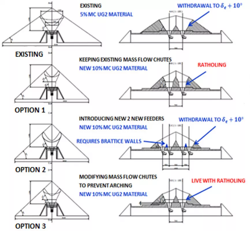
The existing mass flow chute in Fig. 21 created arching problems for UG2 material at 10% moisture content, although it worked for the 5% material. The diagonal length of the top opening of the mass flow chute also didn’t meet critical rathole requirements that were obtained from the test work results. This caused a decrease in operational live capacity due to ratholing. It was also established that the arching dimension (indicated in red) is not far above the actual opening.
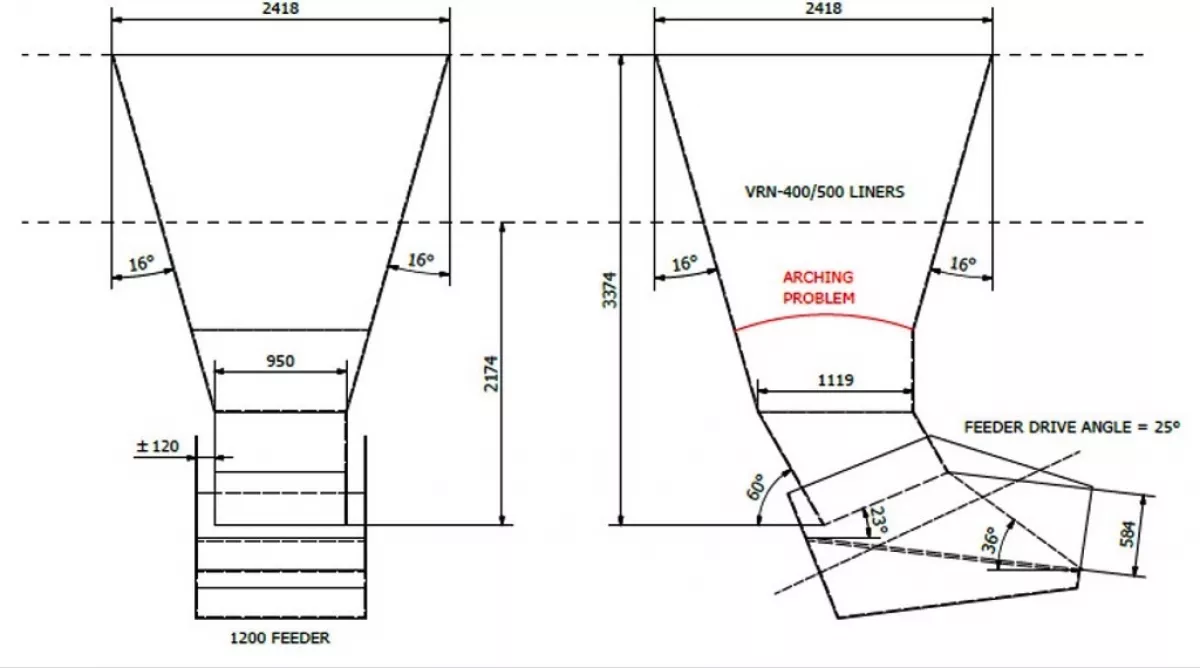
The problem with implementing a new design is that there are many constraints such as tunnel height and downtime to include in the designs. Therefore it was decided to look at solutions improving the design, considering the availability of height. This did not formulate a rigid solution as compared to what could have been achieved in the initial phases of design before construction. The stockpile tunnel height couldn’t have been adjusted to fit all the mass flow requirements. The improved mass flow chute in Fig. 22 adheres to the test work parameters and should eliminate the arching problems for UG2 material at 10% moisture content, although the minimum arching dimension selected was border line and still at risk. The diagonal length of the top opening of the mass flow chute didn’t meet critical rathole requirements, and live capacity would be lost due to ratholing.
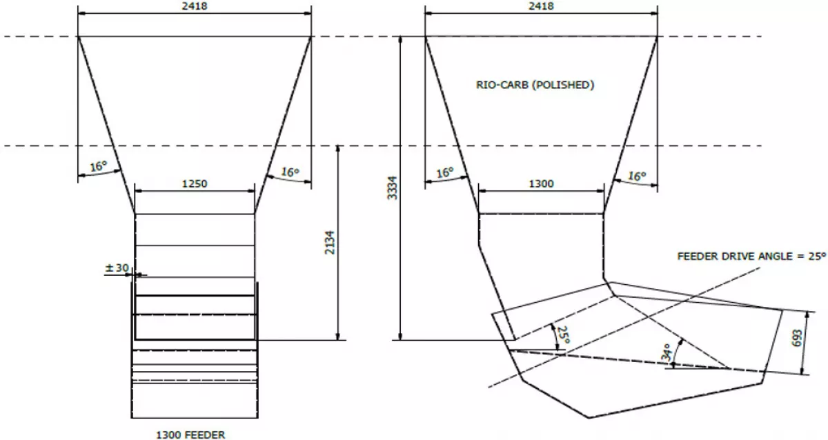
To eliminate the ratholing problem, additional two feeder openings were required, with brattice walls This would stretch the effective diagonal from one mass flow chute to two mass flow chutes combined (in plan-view), meeting required ratholing conditions. Note both feeders should operate simultaneously or in calculated steps. Another improvement was smooth polished Rio-carb liners.
The decision by the client was that an estimated live capacity of ±3 hours would be acceptable, therefore accepting ratholing. Changing the stockpile tunnel by adding two additional feeders would create downtime and affect the operation, therefore this change was discarded. Although no modifications were made to the mass flow chutes, this was required to eliminate the arching problems. It should be highlighted how the effect of moisture combined with fines could increase the material’s cohesive strength and create flowability problems. Therefore it is critical to establish design parameters for materials handling design by means of test work.
■

