

Modernization of conveyor systems in today's coal mines and coalfired power plants should be an essential goal for the management, employees and share holders of the company. It helps to ensure that the mine or plant is running to their optimum capacities, maximising the tonnes per hour and producing the highest quality product with as little impact to the environment as possible. Power plants being built today emit more than 90 per cent less pollutants (SO2, NOx, particulates, mercury) than the plants they replaced from the 1970's, according to the National Energy Technology Laboratory.
Asset optimisation/modernisation has never been more critical in the everyday activities we do at home and at work. Coal is abundant, clean and the most efficient energy source available. Conveyors are the lifeline to any coal-fired power plant’s productivity. No coal = No low cost, clean, abundant, affordable energy. Proper consistent training and periodic inspections of the conveying systems with reliable turn-key installations substantially increases the system’s availability. On-going maintenance is essential to ensuring an incident and injury free workplace while maintaining a productive reliable workforce. All of which are essential to any material handling system and the employees who maintain them.
Properties of Coal
"Coal is the most affordable source of power fuel per million Btu, historically averaging less than one-quarter the price of petroleum and natural gas," according to the National Mining Association. There are four basic varieties of coal (Table 1):
- Anthracite: Sometimes also called "hard coal," anthracite was formed from bituminous coal when great pressures developed in folded rock strata during the creation of mountain ranges. Anthracite has the highest energy content of all coals and is used for space heating and generating electricity. Anthracite averages 25 million Btu per tonne.
- Bituminous: Bituminous or "soft" coal formed when greater pressure was applied to sub-bituminous coal. This is the type most commonly used for electric power generation in the U. S. It has a higher heating value than either lignite or sub-bituminous, but less than that of anthracite. Bituminous coal averages 24 million Btu per tonne.
- Sub-bituminous: Sub-bituminous coal formed from lignite when it came under higher pressure. This coal has a high (25 to 35 per cent) moisture content which raises the risk of spontaneous combustion. A dull black coal with a higher heating value than lignite that is used primarily for generating electricity and for space heating. Sub-bituminous coal averages 18 million Btu per ton.
- Lignite: Increased pressures and heat from overlying strata caused buried peat to dry and harden into lignite. Lignite is a brownish-black coal with generally high moisture and ash content and lower heating value. However, it is an important form of energy for generating electricity, particularly in the American Southwest. Lignite averages 14 million Btu per tonne.
| Coal | Colour | Moisture [%] | Fixed carbon [%] | Heating value [kJ/kg] |
| Lignite | brown | 43 | 20 – 35 | 15,100 |
| Sub-bituminous | black | 26 | 35 – 45 | 20,470 |
| Bituminous | black | 5 | 45 – 80 | 28,890 |
| Anthracite | black (vit) | 2 | 80 – 96 | 30,240 |
The above information is important to power plants today because they might have been designed to burn bituminous coals, but due to the higher costs of this coal they might be switching or what's commonly known as blending in sub-bituminous coal, like we see from the growing Powder River Basin in Wyoming and Indonesia and Australia.
Transfer Point Design
Some recent advancements or modernizations have been accomplished through conveyors designed with new chutes in the transfer points. The number of the new coal-fired power plants burning bituminous coals or steel plants that use metallurgical coal for producing coke, verses the worldwide demand has not been consistent. There is far greater demand than the current amount of plants capable of producing coke or energy. Therefore, we are asking our current mines to mine more coal and our power plants to produce more megawatts (energy). We are asking them to do this most of time using the same equipment that was installed when the mine or power plant was originally started up, sometimes more than 20 to 30 years ago. When the power plant was originally designed it might have been designed for 800 megawatts and today we are asking it to produce more than 1000 megawatts.
A newly designed ideal transfer point chute should be a tight enclosure with dust curtains to reduce the induced air velocity and a direction hood that is either mounted into the existing transfer chute or a newly designed transfer that incorporated a hood into the actual design of the framework around it. The hood will smoothly guide the discharged material through the chute with minimum impact as to not separate the material which would then induce more air. The downward energy of the material stream is converted to flow in the same direction of the downstream conveyor. The use of a spoon type design allows the material stream to enter at a shallow centring angle onto the receiving conveyor which requires minimal acceleration to match the speed of the receiving conveyor belt. This will result in minimizing the impact and wear on the receiving conveyor belt, centre load the conveyor belt which would reduce spillage in the load zone and off centre tracking problems along the troughing side of the conveyor system. Off-centre loading is responsible for poor conveyor belt tracking and consequent spillage, dusting and wear at the skirtboard area throughout the length of the conveyor.
Combined with a well-sealed skirtboard system in the receiving conveyors load zone area, including proper internal liners, roller cassette beds to ensure little or nosag in the load zone as the material is being loaded on to the conveyor belt and a skirt rubber clamping system. The skirtboard system should also include adequate dust skirting material and dust curtains staggered throughout the load zone area which will reduce the induced air velocity from existing out of the end of the skirtboards into the building. Everywhere else along the conveyor system should be made to isolate and contain areas where dust is created. The use of high quality belt cleaners or wash box systems to help eliminate material carryback is another important step to help reduce dust and spillage making the conveyor systems more productive, efficient and safe means of transporting material.
Power Plant Upgrade
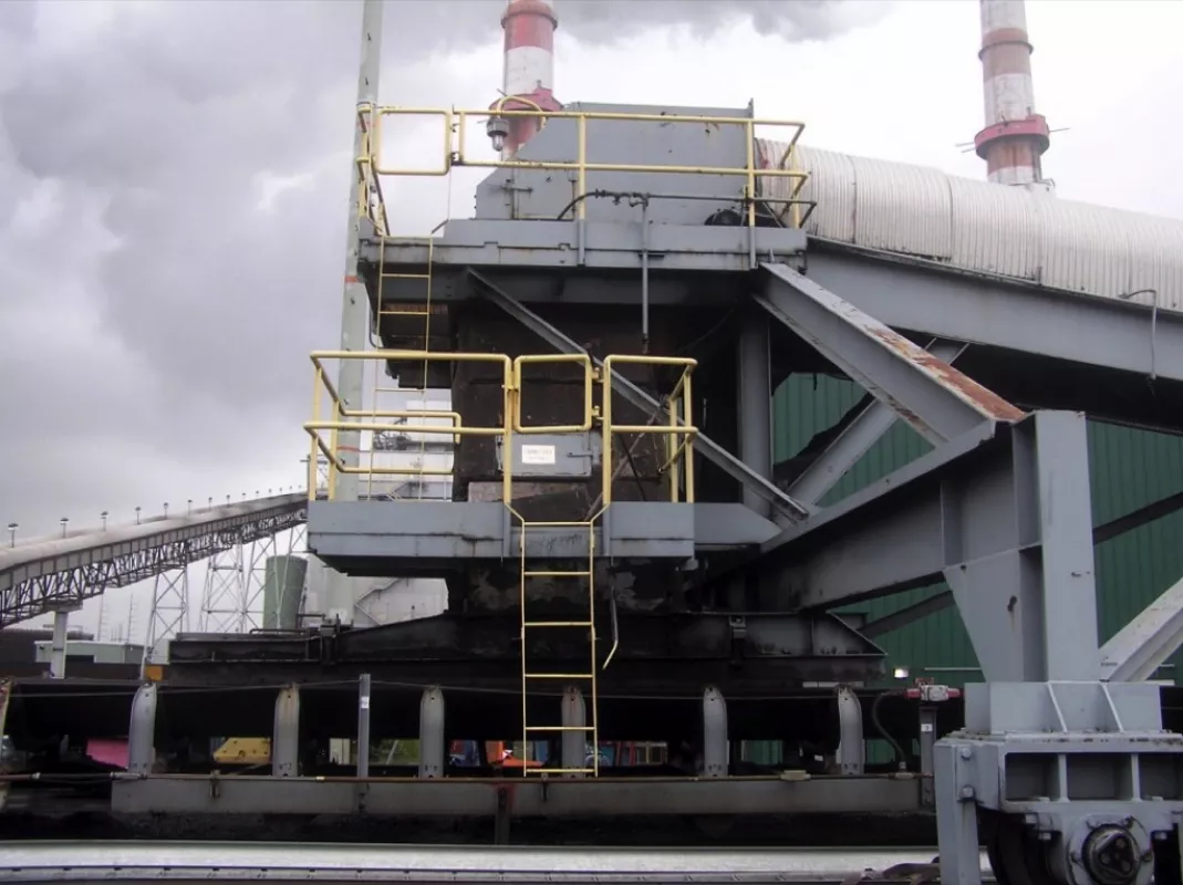
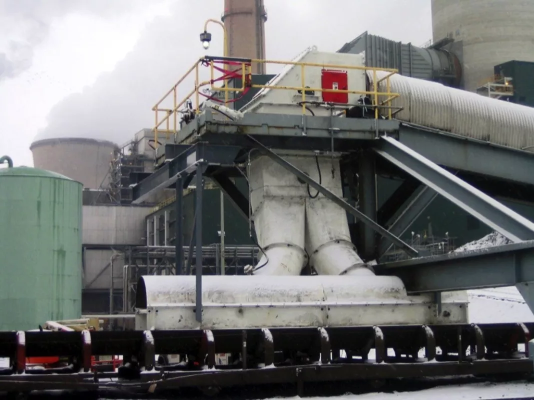
A coal-fired power plant that wanted to upgrade an existing transfer point which had been a major problem area for the coal yard and in turn limited the plant’s ability to keep a consistent supply of coal to the bunkers. While in the reclaiming operation, the chute would buildup and plug with coal fines that stuck together when they were in wet coal or freezing conditions (Fig. 2).
Chute heaters, vibrators and internal baffles were added, but the problem still remained. When the coal was dry it generated more dust at the transfer point and spillage was occurring between the skirtboard and the belt, due to the angle of discharge onto the 1.5 metre receiving conveyor. Off centre loading caused serious conveyor belt misalignment and constant spillage in the load zone. The bypass conveyor is an approx. 1.1 metre (42 inch) wide conveyor belt, which runs at 3.6 metres per second (700 feet per minute) and which has a capacity of 1400 tonnes per hour.
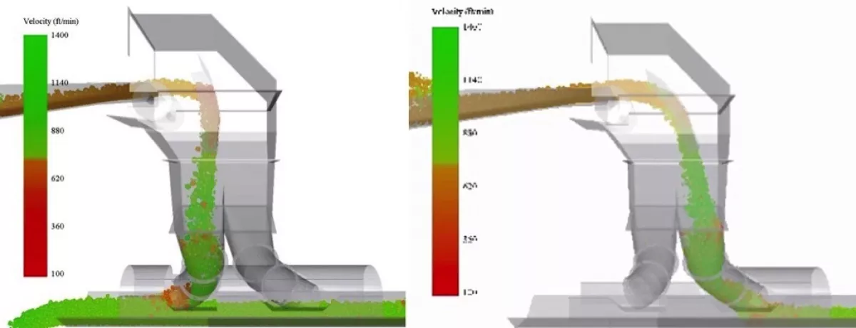
The receiving conveyor has a belt width of approx. 1.5 metre (60 inch), runs at 4.3 metres per second (850 feet per minute) and has a capacity of 3000 tonnes per hour. A new transfer point was modelled and designed using ASGCO's 3-DEM (Discrete Element Modelling) and project management and engineering team to review the current conditions as well as the potential for different types of coals to be conveyed or blend with the existing coal, see Fig. 3.
The main goal of the project was to make a more efficient (no plugging or buildup) and less dust than in the current load zone. Also allowing for current coal (bituminous) conditions as well as the possibility of using new coal (sub-bituminous PRB) coal or the potential to blend both types of coal in the future at the plant. Other goals were for the coal to be loaded onto the receiving conveyor belt, moving in the same direction, speed and in the centre of the receiving conveyor belt, therefore causing less spillage and dust in the load zone and longer run life on the receiving conveyor belt.
The design of the new chute also eliminated corner build-up of the wet sticky coal and reduced the wear due to less impact and not being properly directed that was noticed in the old chute. An upper deflection hood was installed and utilized a hydraulically powered ram that actuated in or out depending if the plant was stacking or reclaiming coal. This design eliminated the problems of flop-gates which can be a maintenance problem for any plant. The deflector hood was automatically positioned in the head chute to direct the coal during either stack out or reclaim. The bottom of the chute incorporated a dual spoon design to operate without buildup and the coal is centre loaded onto the 1.5 metre (60 inch) receiving conveyor belt at the same speed and direction.
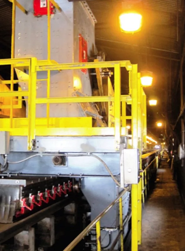
This has resulted in a nearly "dustless" transfer point, dramatically reduced spillage as well as increased life on the receiving conveyor belt, see Fig. 1. There was less wear on the internal liners and centre loading to minimize any misalignment of the conveyor belt as it was being loaded is now a thing of the past. Another major concern for plants handling coal is in bunker house or on the tripper/cascade floors where the coal is being loaded into the bunkers or silos prior to being pulverized and being injected into the boiler. Because these conveyors are located inside the plant, the combustible dust issues are exemplified. Many governmental regulations, like the United State's OSHA NEP combustible dust requirements, have made it mandatory for all operators of coal fired power plants to address any airborne dust issues.
A Dual Tripper Car System
The installation shown in Fig. 4 was an existing dual tripper car system with two (side-by-side) tripper conveyors, rail mounted, handling a blend of sub-bituminous and bituminous coal with a particle size of 25.4 millimetre (1 inch) minus. The conveyors of the system, that feeds the coal bunkers below, are approx. 0.9 metres (36 inch) wide and run at 2 metres per second (400 feet per minute), handling 600 tonnes per hour, each.
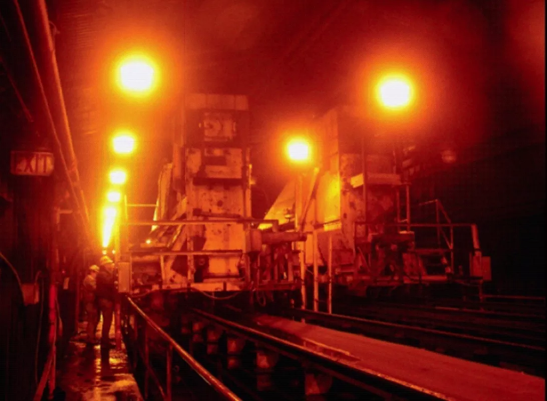
The major problems were the large amount of airborne dust (see Fig. 4) created from handling the coal and the increased tonnages demanded from the plant. Another concern was the timeline and installation issues of being located ten floors above the ground and having to dismantle the existing tripper cars and transfer chutes was on a tight schedule and had to be accomplished one at a time so at least one of the trippers could run during the day to fill the coal bunkers below.
Two new tripper cars were modelled and designed using ASGCO's 3-DEM material modelling software as well as reviewed with engineers, maintenance and operators from the power plant. Together they came up with the new design that would meet all the goals of the project. The primary goal of this project was to create a nearly "dustless" transfer of coal and allow the coal to be either loaded down to the bunkers or loaded back onto itself, moving in the same direction, speed and in the centre of the receiving conveyor.
The new design improved the flow of the coal and the new combination of internal liners also improved the wear ability of the liners. The combination of the X-Wear MDX liners, a combination of ceramic cylinders encased in rubber, for the impact area and the chromium carbide overlay plate (double pass and polished) was the answer to the sliding abrasion issues prior to the new design.
As shown in Fig. 5 the amount of airborne dust and spillage is virtually eliminated with the new tripper design. Clamp mount skirting, dust curtains and skalper belt cleaners further aid in the elimination of any fugitive dust and carryback helped the plant meet and exceed its goals for the project. The newly installed transfer chutes now operate with improved coal flow through the tripper system without buildup and less wear in the internal liners nearly eliminating all spillage and any significant amount of airborne dust. A nearly "dustless" transfer point. In conclusion, it is necessary for any coal mine or coal handling facility to look at ways to improve productivity, efficiency and safety.
A Note from the Editor
For all statements in this article that refer – directly or indirectly – to the time of publication (for example “new”, “now”, “present”, but also expressions such as “patent pending”), please keep in mind that this article was originally published in 2012.
■

