

Splice Measurement Matrix as per SANS
- Permanently embossed marks shall be placed on the inside four corners of the splice on the bottom cover according to Fig. 2.
- The sum of the dimensions shall not change by more than 1 %. The base line initial measurements shall be made on the low tension return side of the conveyor when the belt is under tension at a recorded datum point and always re-measured at the same datum point and under the same tensioning conditions.
- Initial measurement to be done by splicing constructor.
- Should the tensioning conditions change, a new set of base line dimensions shall be established.

Scanning
In the event of steel cord reinforced belting being used, a baseline scan should be done upon completion of splices to verify correct layout of cords and splice integrity. This can be done using either X-ray or magnetic flux leakage scanning. Regular follow-up scans should then be performed at agreed intervals. The follow-up scans must then be compared to the baseline scan, checking for any changes or deviations from the original.


X-ray scanning is however, not cost effective and does have some safety concerns linked to it. With the recent advances in the accuracy of magnetic flux leakage scanning it is possible to obtain a very accurate representation of the splice and it is possible to determine small deviations within the splice. The systems can also be permanently installed on the structure with the added benefit of offering a full belt scan to determine the condition of all the cords within the belt.
In the magnetic flux leakage scan image, the cords are magnetized and any leakage in the magnetic flux is detected by sensors mounted in a sensor array. The image in Fig. 3 is of a two-stage splice showing no deformation in the splice alignment or stray and damaged cords in the splice area (Fig. 4).
Further research is required on the effect of positive and negative bending of splices, different types of splices, including the effect of the frequency of bends on a splice, for instance at the head and snub pulley, or from a high tension snub pulley into a drive pulley. The specifying of a minimum relaxation distance between two bends in opposite directions should be investigated and documented (Figs. 5 and 6).


Material Compatibility Testing Guidelines for Steel Cord Reinforced Conveyor Belting
Compatibility of splicing material and belt is assessed by testing the adhesion of the splicing material to the aged belt cords. For this purpose the preparation of an H-block test piece is required (Figs. 7 to 11).
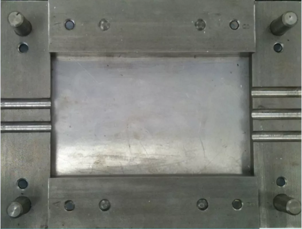
Fig. 7: H-block mould
|

Fig. 8: Splicing compound in mould
|
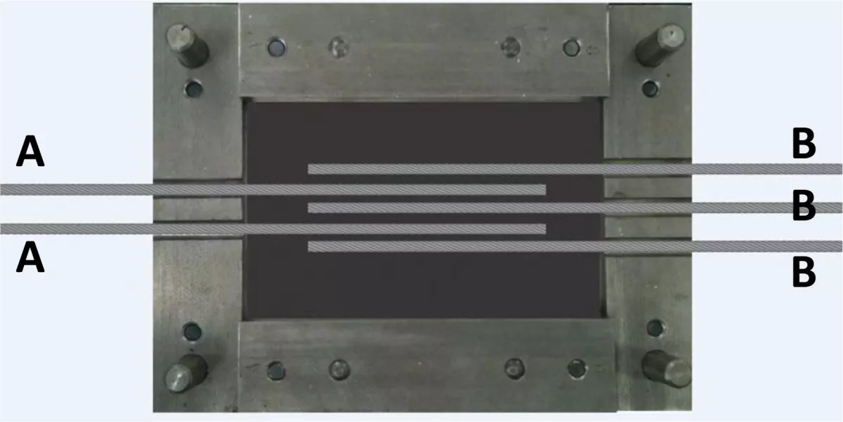
Fig. 9: H-block assembly
|

Fig. 10: H-block assembly
|

Fig. 11: Completed H-block
|
The H-block consists of three cords vulcanised in a splicing material rubber matrix. A minimum of four H-blocks are required for testing.
H-block Construction
Consider the leading belt as A and the trailing belt as B. Cords must be stripped in accordance with procedure for the preparation of a splice.
Assembly and Cure
Two H-blocks are constructed by using cords from belt A either side of a cord from belt B. (A,B,A,B,A) and two H-blocks constructed by using cords from belt B on either side of cord from belt A (B,A,B,A,B).
After curing, the H-blocks should be left overnight to stabilise. Standard pull-out testing is then performed.
A minimum pull-out figure would be 12 x cord diameter. Anything less, and a splice design may not have a sufficient safety factor if designed on 8 x cord diameter, normal.
A result of less than 10 x cord diameter pull-out (expressed in kN/m) means rejection of the splicing compound.
When the H-blocks have been tested, the mode of failure is noted, i.e. bonder to bonder, or cover to bonder.
Cover to bonder is preferable as a greater proportion of splice strength relies on bonder to bonder adhesion.
In addition, two H-blocks (one A,B,A and one B,A,B), must be subjected to dynamic cyclic testing to determine the compound’s resistance to fatigue.
The set points would be 36% and 3.6% of the actual achieved pull-out test results.
Some mining companies insist on 7 000 cycles minimum, with no evidence of cord pull-out.
The cyclic blocks are again tested in the tensile test apparatus to determine any fall- off compared to the original lab-built H-block pull-outs.
The figures should be about 95% minimum. Anything less must be rejected.
Plied Belt Testing
The same type of testing is applied to plied belts, using whichever compound is applicable. A lab pad is constructed containing all plies, and subjected to adhesion tests after allowing stabilisation. Results must be at least equal to new belt adhesion test results.
Extrapolation should result in a figure of approximately 65% of full belt strength when testing a four-ply belt if a reduced stepped splice is built.
Conclusion
Rubber, as do humans, ages. How this aging process is managed may not be an easy and straightforward task.
To ensure the safe and efficient operation of any spliced conveyor belt, it is important to ensure that the best possible materials and the best matched materials to perform the tasks are used, in conjunction with good practices, correct and functioning equipment, and operation by qualified and competent personnel.
If the splice process is well managed, especially on steel cord reinforced belting, it should be possible to expect such a splice to last the life of the belt. If splices are regularly monitored for deterioration, early detection of any kind of damage can be managed, and possible losses due to a splice failure minimised by performing preventative maintenance.
Acknowledgement
This article is based on a presentation of the author during Beltcon 19, 2./3. August 2017 in Johannesburg, South Africa. The article was published in Issue 4/2017 of "bulk solids handling" with kind permission of the IMHC/Beltcon.
■
