

Disadvantages

- High frequency of nuisance trips have been reported. Resulting in system being bypassed.
- Relative high initial cost
- Transmitting and receiving units susceptible to damage through spillage due to its proximity to the belt (Fig. 10).
- Long downtime for retrofitting damaged sensor loop coils.
The Future – Now
Advances made in RFID technology (Fig. 11) have made it possible to use this type of systems in condition monitoring and in particular in rip detection systems.
RFID – Radio Frequency Identification is the wireless use of electromagnetic fields to transfer data, for the purpose of automatically identifying and tracking objects fitted with identifying tags.
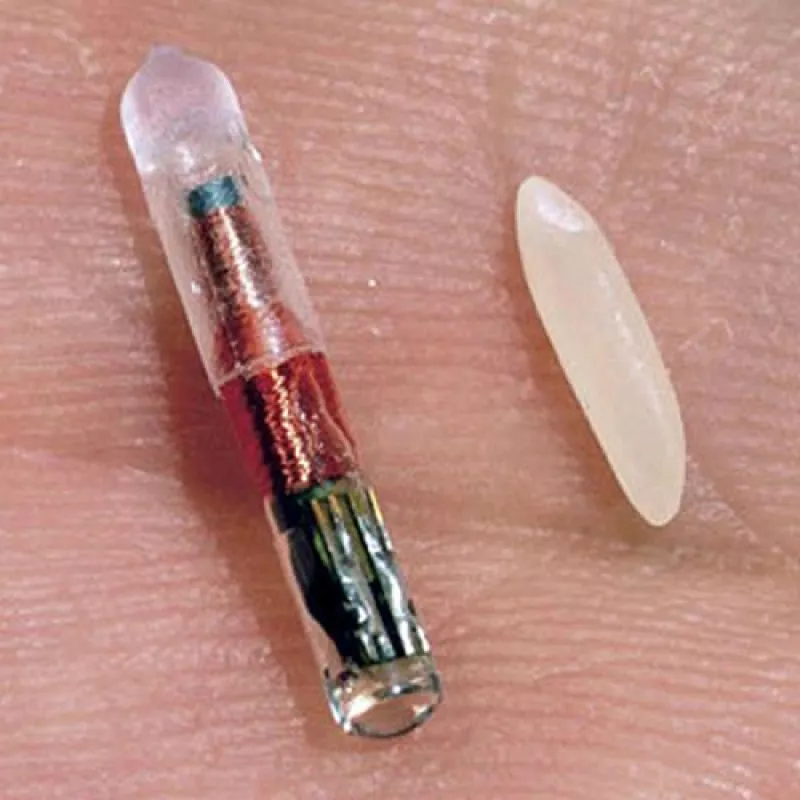
Passive tags are powered through electromagnetic induction from magnetic fields produced near the reader. Active tags are fitted or connected to a power source. RFID Tags does not have to be in line of sight of the reader to be read or identified.
RFID have been integrated into sensor loop systems during the last couple of years. The function of these tags was mainly for identification of the sensor loops and to facilitate in the identifying of the location of the damage to the belt.
Recent advances made in RFID technology have given rise to the development of a rip detection system where the RFID tag forms the backbone of the system. The RFID tag is no longer used for identification purposes only.
This system utilizes UHF RFID tags. UHF RFID tags incorporate the use of electromagnetic or electrostatic coupling in the radio frequency portion of the spectrum to communicate to and from the tag.
UHF RFID tags operate in the 800 to 950 MHz range and use less power and are better able to be read through nonmetallic substances. This makes it ideal for use in rubber products. UHF tags offer better range and can transmit data faster. UHF tags can be read at speeds in excess of 20 m/s.
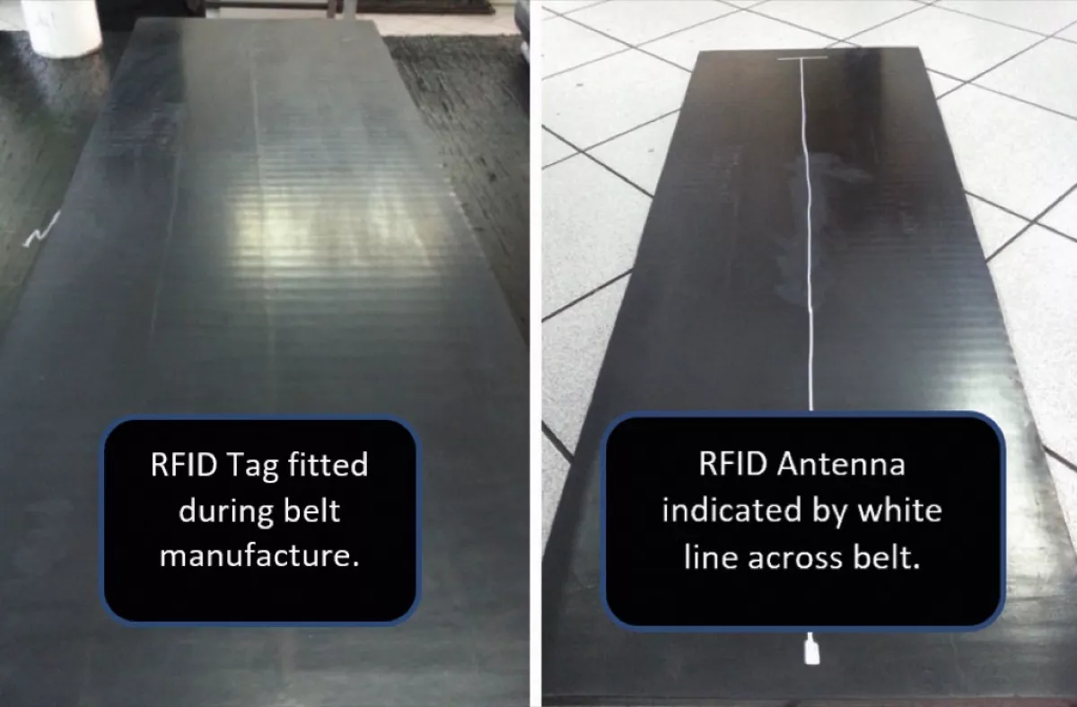
The recently developed RFID Rip Detection system utilizes UHF RFID tags with a single strand antenna running across the width of the conveyor belt in place of the more traditional sensor loop. This means that the antenna size is reduced considerably from approx. 400 mm wide to only 100 mm wide. The thickness of the antenna and RFID tag is less than 3 mm in diameter which lends it to the insertion in belting with thinner covers.
Due to the tags resistance to high temperatures and pressures it can be fitted to any belting during the manufacturing process. Plied, steel cord and PVC nitrile belting can now be fitted with rip detection loops (Fig. 12).
A major advantage in this development is the cost of the antennas and the ease of retrofitting to an existing belt. At roughly 1/10th of the price of a standard sensor loop the antenna can be retrofitted to any existing belt with sufficient covers in approx. 2 hours, compared to 6 to 8 hours needed to retrofit the standard sensor loop.
Due to the low cost of the antenna it makes sense to reduce the intervals at which the antennas are inserted in the belt, it is now possible to limit the potential loss of belting due to rips to a minimum. 10 to 15 m intervals as opposed to the standard 50 m with traditional sensor loops.
A rip of 50 m or more will in most cases make it necessary to fit an insert in the belt and two splices. By reducing the potential loss of belting to 10m there is no need for an insert or two splices, further reducing down time and production loss.

The system consists of the following,
- UHF RFID antenna – Embedded in conveyor belt (Fig. 12)
- RFID reader (Fig. 13)
- Master Control unit (Fig. 14)
Once installed, the system requires one revolution of the belt to memorize the individual RFID tags and the distance between each tag. It then switches automatically to active mode once the first tag is recognized.
In the event of the master control not reading the expected tag after the memorized number of pulses it will stop the conveyor.

UHF RFID tags are read and write capable which makes it possible to write information to the tag. Up to 8 pages of text information can be written to the tag. Conveyor belt data books, quality documentation, installation dates etc. can now be written to the tag and accessed on site using a handheld scanner.
Thus, through the cost effective use of the latest technology available it is possible to reduce the risk of catastrophic longitudinal rips in all conveyor belting and minimize to impact in such an event
Belt Thickness, Wear Measurement/Monitoring
Another method of condition monitoring revolves around the measurement of belt thickness at regular intervals in order to determine the wear rate and pattern of any particular belt. Through this measurement and tracking of the wear it is possible to, with a fair degree of accuracy, determine the remaining belt life and identify any abnormal wear patterns which might indicate ineffective or damaged components in the conveyor system.
A major drawback with this has always been the time required to do the measurements and to create a useable report. (Figs. 13 and 14).
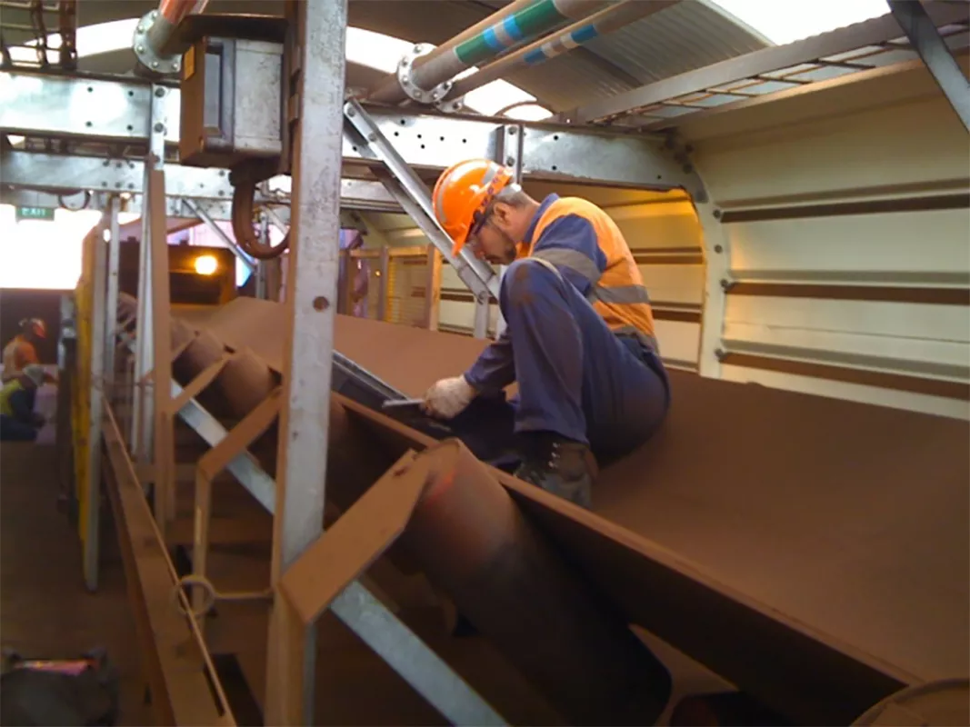
Fig. 15: Measurement is done with handheld ultrasonic measuring equipment.
|
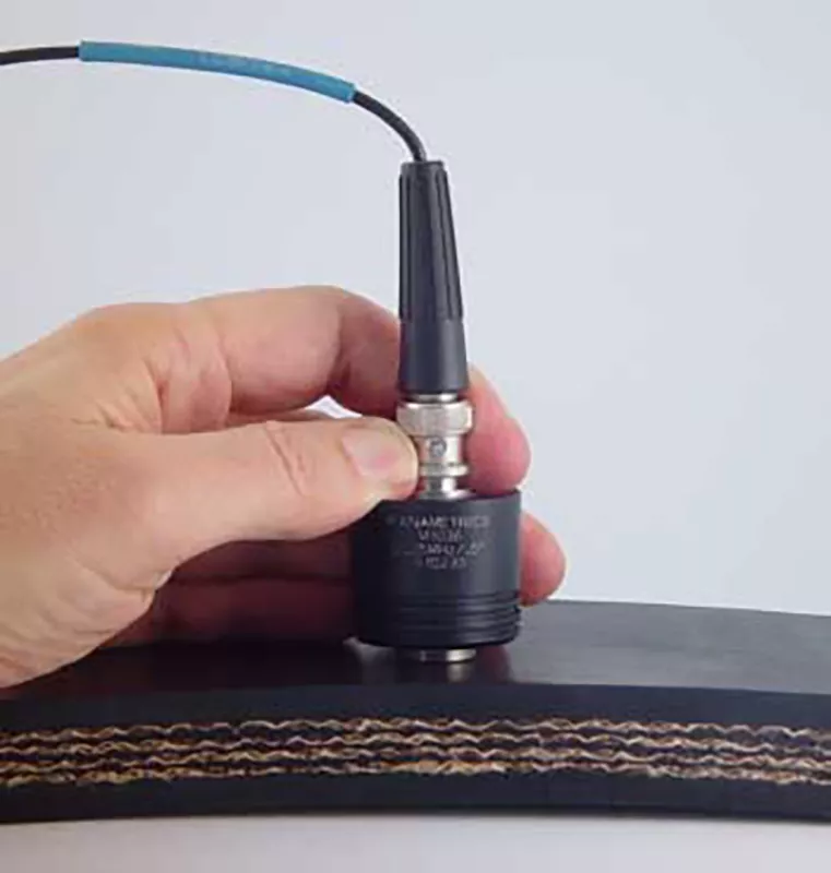
Fig. 16: Handheld ultrasonic thickness measurement tool. (Picture: ©Olympus Corp.)
|
The process most often requires a full lock-out of the system and only when the system is safe will it be possible to measure the belt. Measurements are taken at pre-determined intervals across the width and length of the belt. This could take up to 8 hours depending on the accuracy required. All these measurements are then used to plot a graph of the wear on the belt. (Figs. 17 and 18).
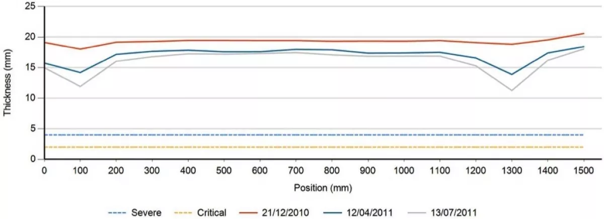
Fig. 17: A graph of thickness measurements showing cover damage by skirting rubber.
|
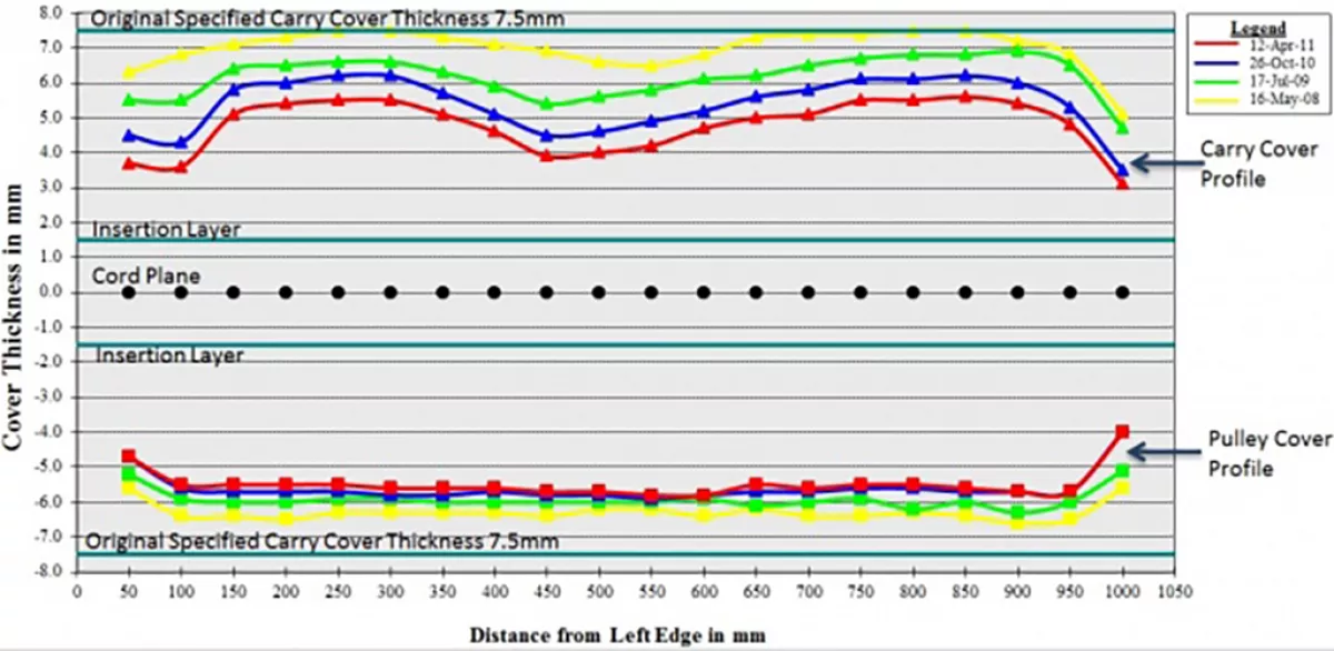
Fig. 18: A graph showing wear profile at one point across belt width.
|
Various systems have been developed in recent years to measure this more accurately. From using laser modules (Fig. 19) to electro mechanical systems to lower a measuring unit down to the belt to perform the measurements (Fig. 20).
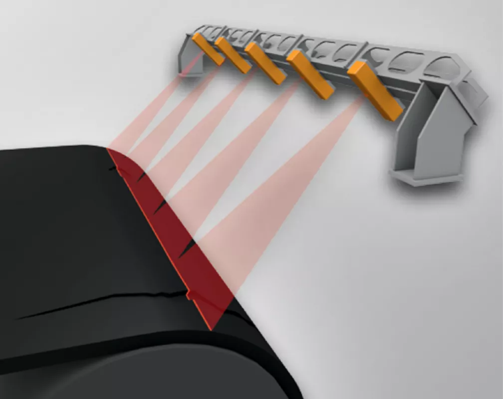
Fig. 19: Laser modules. (Picture: © ContiTech AG)
|

Fig. 20: Electro mechanical unit. (Picture: © Beltscan Systems Pty Ltd.)
|

Enhancements in the robustness and accuracy of ultrasonic sensors have made the development of cost effective and reliable belt thickness measurement systems possible. Continuous belt thickness monitoring has been made possible by combining RFID and ultrasonic technology.
Current systems offer the possibility to measure the thickness of any flat conveyor belt across the full width and for the full length of the belt.
All this is done during production. The only downtime is when the system is installed during normal planned maintenance.
The system consists of the following elements:
- Master Control Unit
- RFID Reader
- Ultrasonic sensor unit

The latest ultrasonic sensors utilized are capable of measuring 100 samples per second at an accuracy of 0.05mm.
The ultrasonic sensor array is mounted on the return side at a distance of approx. 150 mm from the belt facing the top cover. As most wear will occur on the top cover, measurements are taken from this side in order to determine the full belt thickness.
Due to the accuracy of the sensors it is crucial for the belt to be free from belt flap or any oscillations. For this reason calming idlers are fitted with the sensor array (Figs. 21, 22).
A RFID tag is installed in the belt. The system recognizes this tag and triggers the measurement for one full belt cycle. The information is processed and stored. Data for each measurement cycle is date and time stamped and saved.
Once installed the master control unit can be linked to the control room for remote access to information and measurement results (Figs. 23, 1). Measurement results are immediately available. By utilizing the information gathered it will be possible to detect excessive and abnormal wear and rectify the problem before a catastrophic failure can occur (Fig. 24). The wear rate will enable the end-user to more accurately determining the remaining belt life and therefor optimize their planning and reduce stock holding.
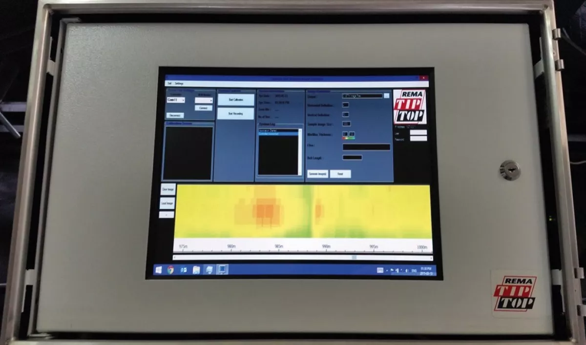
Fig. 23: Belt thickness monitor master unit.
|
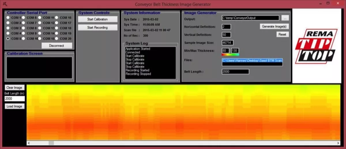
Fig. 24: Belt thickness monitor indicating wear on edge of belt.
|
Conclusion
Through the effective use of ever changing and developing technology it is now possible to operate and maintain equipment more safe and efficiently than ever before. The ever changing industrial environment will in future put more challenges to us to ensure safe and efficient operations. It will require constant R&D, development and application of technology at our disposal realize this. Who knows what the future holds?
Acknowledgement:
This article is based on a presentation of the author during Belton 18, 5./6. August 2015 in Johannesburg, South Africa. The article was published in Issue 2/2017 of “bulk solids handling” with kind permission of the IMHC/Beltcon.
■
