

3.4. Stage 3: Material and Contact Model to assess Flow
One of the key aspects of chute design, to have a smooth material flow without blockage, should never be overlooked regardless of the nature of flow of bulk materials. To test the flow of a truly cohesive material through the chute Hertz-Mindlin with JKR contact model was used. This contact model enables to model a material with a strong cohesive behaviour at low contact forces.
Since there are no determined methods to calibrate the cohesive energy and the translation to the flowability of bulk solids, a qualitative calibration method is followed. A very cohesive material was modelled according to Hill’s classification [16] by trial and error. A poured angle of repose of 60° was achieved with a cohesive energy of 35 J/m2. Other material properties remained unchanged. First the particle bed formation in the stagnant zones of the designs is created by assigning high cohesion energy (500 J/m2) to the particles in rest and 400 J/m2 to the coal–chute interaction. Then a new simulation is started with cohesive energy of 25 J/m2 with the particles in rest and 35 J/m2 with the newly generated particles.
4. Results
4.1. Performance of designed Chutes
Wear profiles of the three designs are shown in Fig. 10. Horizontally the three designed concepts are shown with vertically the four simulated orientations. It can be clearly seen that different wear zones exist with different orientations of the wear plate under the telescopic chute.
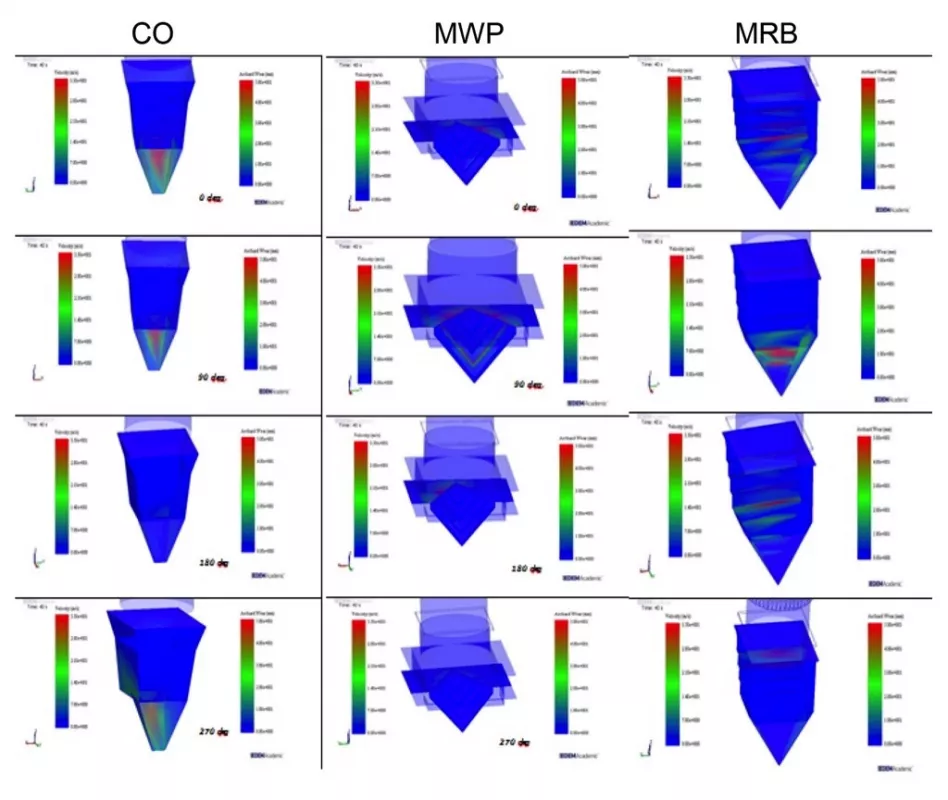
Table 2 shows that all three chute designs experience less wear compared to the current design. A variation in the different orientation of the telescopic chute can be seen; at 90° the reduction compared to current design is the least. It is found that the chute with modified wear plate with ribs exhibits reduced wear because of the formation of material bed between ribs and material on material interaction, while in the chute with multiple rockboxes, energy is dissipated over a wider surface area rather than material on material interaction.

The total energy dissipated (Table 3) is considerably reduced at the modified wear plate design. This is mainly due to the formation of the particle bed between the ribs. In case of chute with central opening the total energy dissipated at the surface is not as good when compared to the results of the modified wear plate. Whereas with the chute with multiple rockboxes, the total energy dissipated is much higher than other designs.

From Table 4, it can be seen that the discharge velocities of modified wear plate and the chute with multiple rockboxes are also considerably lower when compared to the current design and the chute with central opening. The low velocities of the particles in the chute with mini rockboxes can be attributed to the total energy dissipated in the chute by the particles sliding horizontally after the first impact and dissipating low energies multiple times as they slide down the rockboxes for positions 0 and 180°.

Velocities are considerably higher at 90° and 270° positions because at 90°, the particles fall closer to the outlet of the chute. In case of the modified wear plate, the velocities are normalized to a range of 3.5 m/s for 0°, 180° and 270° positions due to the material on material impact while at 90° the velocity is higher at 4.93 m/s owing to the proximity towards the outlet. Based on the chosen KPI, the maximum wear depth, the chute with modified wear plate and the chute with multiple rockboxes are most promising. However, the performance of the chutes with respect to flowability when the telescopic chute is in retracted position needs to be investigated.
4.2. Stage 3: Flow
Fig. 11 shows the difference in spatial distribution of the particle flow in extracted and retracted position of the telescopic chute. The bulk material flow is concentrated on one side inside the telescopic chute and the impact location on the rock box chute varies with the telescopic chute rotation of 360°.

In Figs. 12 and 13 the flow through the chute with mini rockboxes and the modified wear plate with ribs is illustrated for cohesive material. Overall, it can be seen that the particle flow is ensured even if there is an agglomeration happening as much as the particle build up. For transfer of materials at high velocities (>15 m/s), chutes with rockbox concepts seem to be a best option. In Eurosilo application, where the impact pressure and the energy of the particle stream is very high, the material flow can be maintained if there is enough cross-sectional area at the point of lowest velocity of the bulk material and maintaining particle-particle contact to reduce wear.

Fig. 12: Flow in retracted position of the telescopic chute with mini rockboxes. (Picture: © Technical University Delft)
|

Fig. 13: Flow in retracted position of the telescopic chute with modified wear plate. (Picture: © Technical University Delft)
|
5. Conclusions
The aim of this study was to improve the design of the wear plate/chute in the Eurosilo. Two designs have shown significant improvement based on DEM simulations of a single type of coal. These designs have lesser wear rates at the most extreme situation (extracted telescopic chute) while maintaining flow when the incoming energy is the lowest (retracted chute). Further work is required on testing different kinds of materials with the design in the DEM simulation environment. However, to ensure realistic results quantitative calibration of the material properties is required.

